



MEMS Gas Sensors
MEMS gas sensors combine microfabricated hotplates, gas-sensitive films and compact semiconductor packaging to reduce thermal mass, power consumption and response time. They are a key platform for modern MOX sensing, portable gas detection, indoor air quality, automotive electronics and electronic-nose systems.

Technology overview
What is a MEMS gas sensor?
A MEMS micro-hotplate heats only a tiny suspended structure, reducing the energy required to reach sensing temperature and enabling faster thermal transitions.
Why MEMS matters
- Miniaturization: sensing elements can be reduced to millimeter-scale or smaller structures.
- Thermal efficiency: only the active membrane needs to be heated.
- Fast control: low thermal mass allows rapid heater changes.
- Array integration: multiple channels can be combined for broader gas fingerprints.
- Digital integration: MEMS elements fit naturally into modules with ASICs, MCUs and compensation algorithms.
Microfabricated architecture
What is inside a MEMS gas sensor?
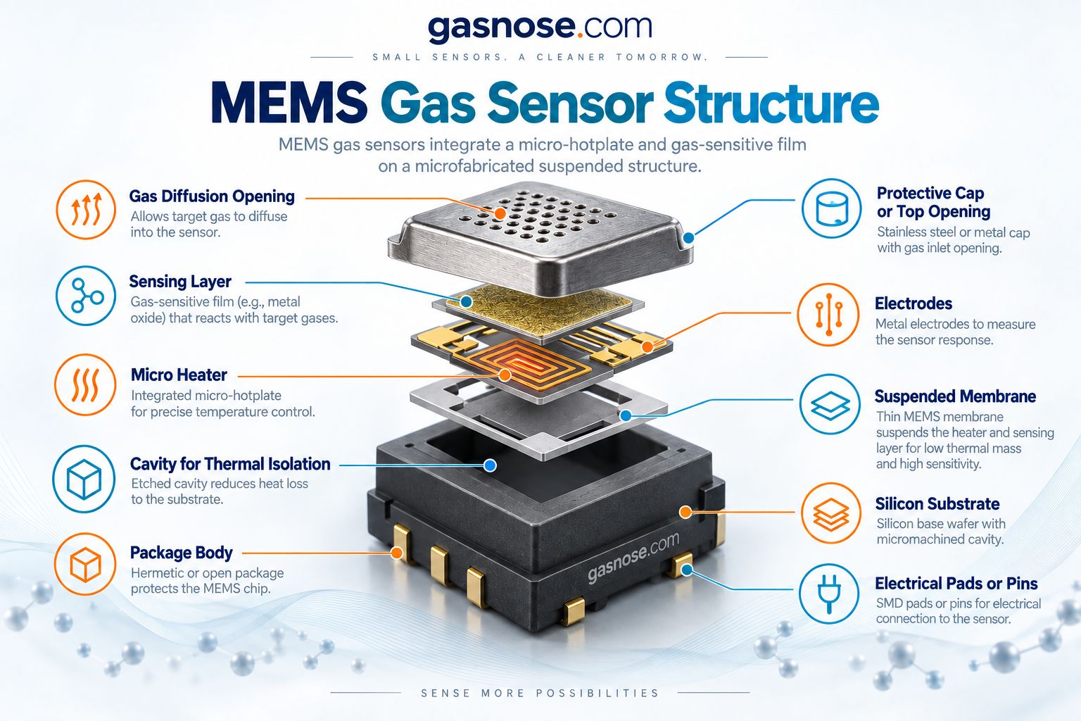
A MEMS gas sensor uses microfabrication to thermally isolate the active area from the bulk silicon substrate. The exact stack varies by manufacturer, but the core functional blocks are similar.
Gas diffusion opening
Allows the target gas to reach the active sensing film while the package protects the MEMS die.
Gas-sensitive layer
Often a metal oxide or catalyst-enhanced film whose electrical properties change during gas exposure.
Micro heater
Raises the sensing layer to the required operating temperature using minimal heated mass.
Suspended membrane
Thermally isolates the hotplate from the substrate and reduces heat loss.
Electrodes
Measure resistance or conductivity changes across the sensing film.
Silicon substrate + package
Provides mechanical support, electrical connection and compatibility with SMD assembly.
Working principle
How does a MEMS gas sensor work?
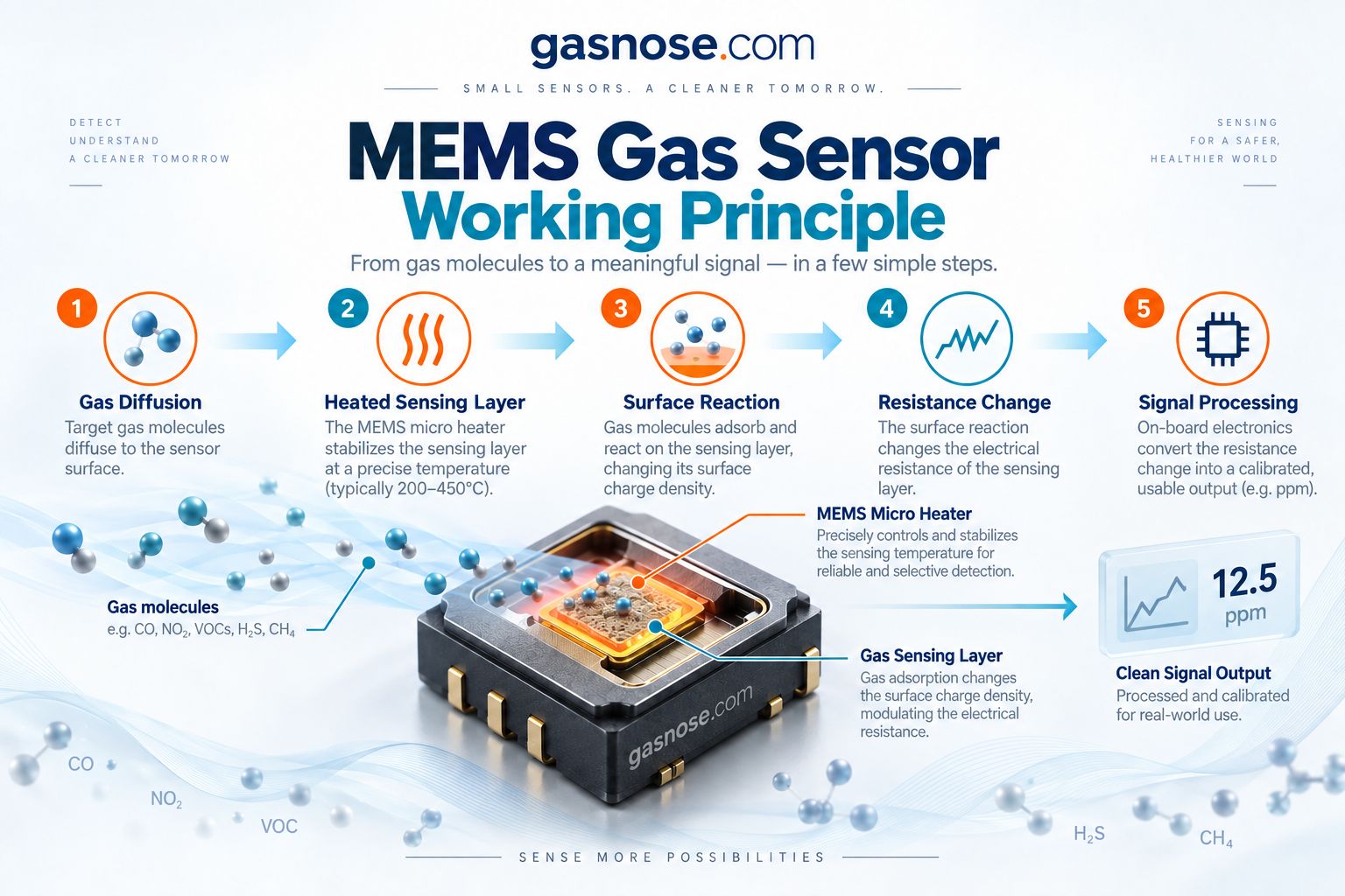
Five-step sensing chain
- 1. Gas diffusion: the gas enters through the package opening.
- 2. Heating: the micro-hotplate stabilizes the sensing layer at the required temperature.
- 3. Surface reaction: gas molecules adsorb, react or modify the active surface state.
- 4. Resistance change: the sensing film’s electrical response changes.
- 5. Signal processing: an analog front end or digital module converts the response into useful information.
Technology comparison
Traditional MOS vs MEMS MOX gas sensors
Traditional heated MOS sensors and MEMS MOX sensors can use similar surface chemistry. The major difference is how the sensing layer is heated, packaged and controlled.
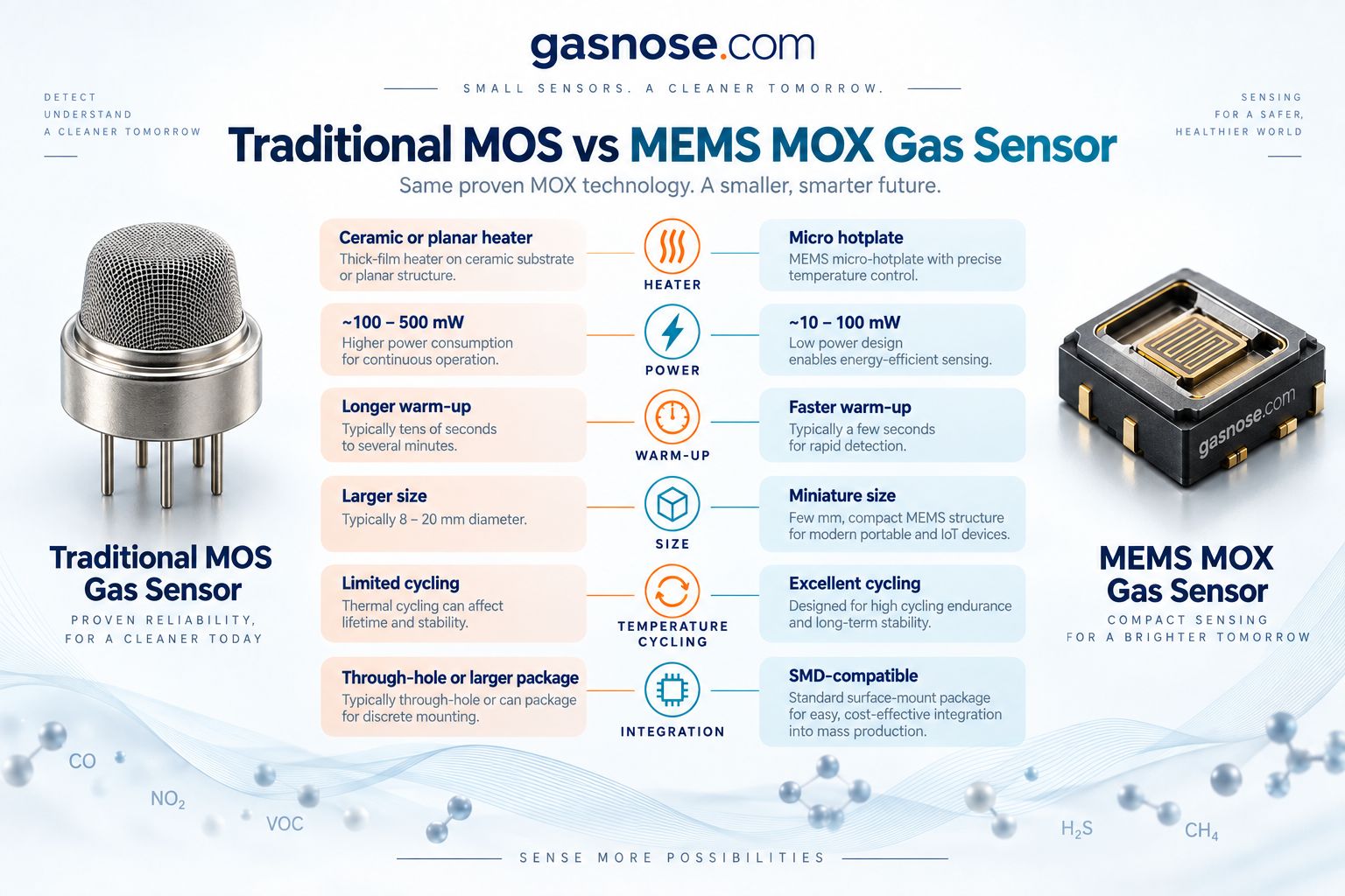
| Design factor | Traditional MOS | MEMS MOX |
|---|---|---|
| Heater architecture | Ceramic or planar heater | Suspended micro-hotplate |
| Thermal mass | Higher | Very low |
| Power consumption | Typically higher | Typically lower |
| Temperature transition | Slower | Fast |
| Temperature cycling | Possible but less flexible | Well suited to rapid cycling |
| Package | Through-hole / larger ceramic or metal package | Compact SMD package |
| Best fit | Mature alarms, appliances, industrial designs | Portable, smart, battery-aware, multi-feature sensing |
Core MEMS technology
Why the micro-hotplate changes gas sensor design
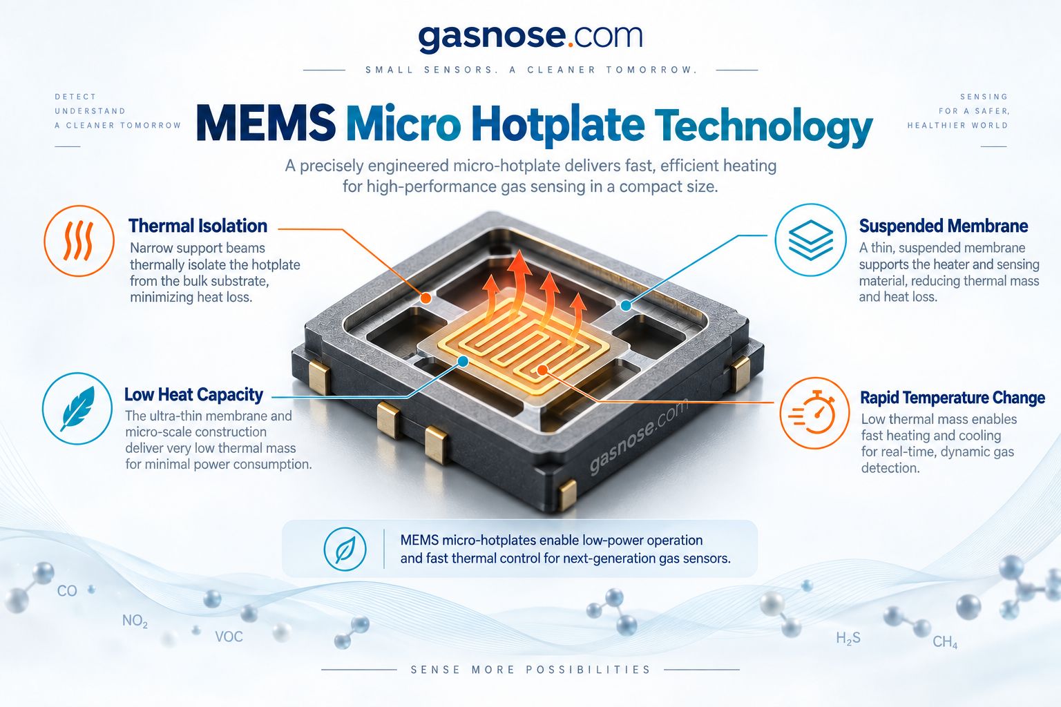
The micro-hotplate is the core architectural advantage of many MEMS MOX sensors. Rather than heating a large ceramic body, the device concentrates heat in a suspended micro-scale region.
Thermal isolation
Narrow support beams and suspended membranes reduce heat conduction into the bulk substrate.
Low heat capacity
Only a tiny mass must be heated, reducing energy demand.
Rapid temperature change
Fast heating and cooling support short duty cycles and advanced heater profiles.
Precise control
Multiple temperature steps can be used to expose different reaction regimes on the same sensing surface.
For battery-powered products, “low power” should be evaluated at the complete operating profile level—not only by looking at one heater number. Duty cycle, warm-up strategy and sampling interval all matter.
Gas fingerprinting
Temperature cycling can create richer gas response fingerprints
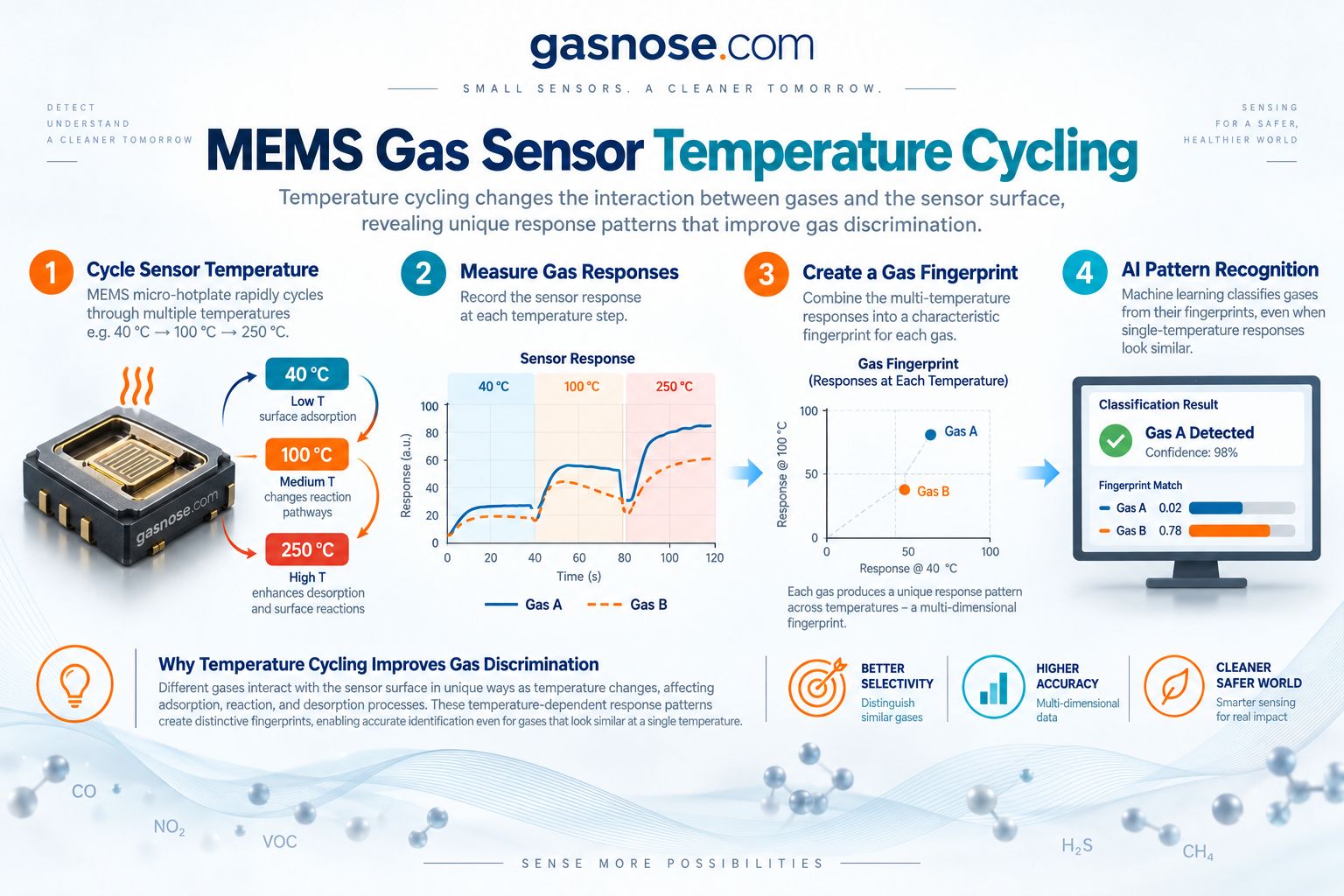
Typical workflow
- Cycle the heater through two or more temperature steps.
- Measure response at each temperature and during transitions.
- Extract features such as amplitude, slope, time constants and recovery.
- Create a fingerprint from multi-temperature responses.
- Classify the pattern with rules, multivariate analysis or machine learning.
This is one reason MEMS hotplates are valuable for electronic-nose systems: the heater itself becomes part of the sensing strategy.
Engineering strengths
MEMS gas sensor advantages
Engineering limitations
What MEMS does not automatically solve
Sensor-level limitations
- Cross-sensitivity to other gases and VOCs
- Temperature and humidity influence
- Baseline drift and aging
- Siloxane and chemical contamination
- Material-specific response and recovery behavior
System-level limitations
- Calibration still depends on the real gas matrix
- AI models need representative training data
- Enclosure airflow can dominate response time
- Low heater power does not guarantee low total system power
- Digital output does not automatically mean absolute gas selectivity
Application landscape
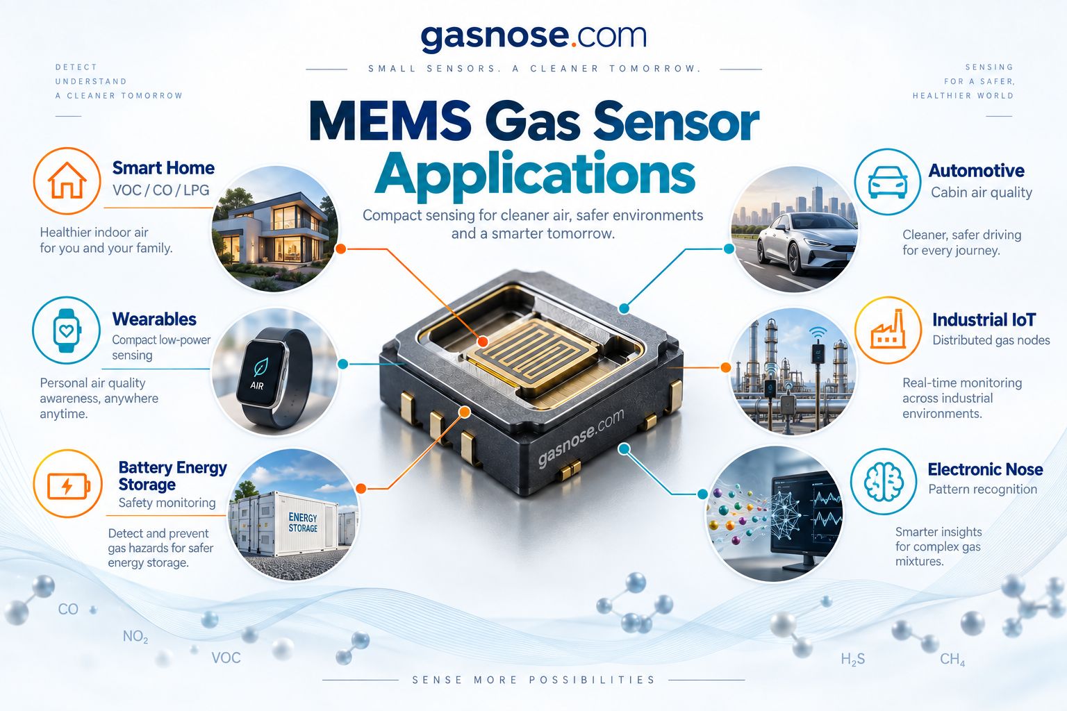
Where MEMS gas sensors are used
Smart home
VOC, odor, smoke and combustible-gas sensing for appliances, ventilation and connected safety devices.
Automotive
Cabin air quality, pollution intake control, odor sensing and intelligent HVAC systems.
Wearables
Compact personal air-quality monitoring where size and power budget are constrained.
Industrial IoT
Distributed gas nodes, smart equipment and connected environmental monitoring.
Battery energy storage
Compact multi-gas sensing can support early-warning architectures when the selected gases and validation strategy match the failure mechanism.
Electronic nose
Multi-channel or multi-temperature pattern recognition for odors and gas-mixture classification.
OEM integration level
MEMS gas sensor element vs module
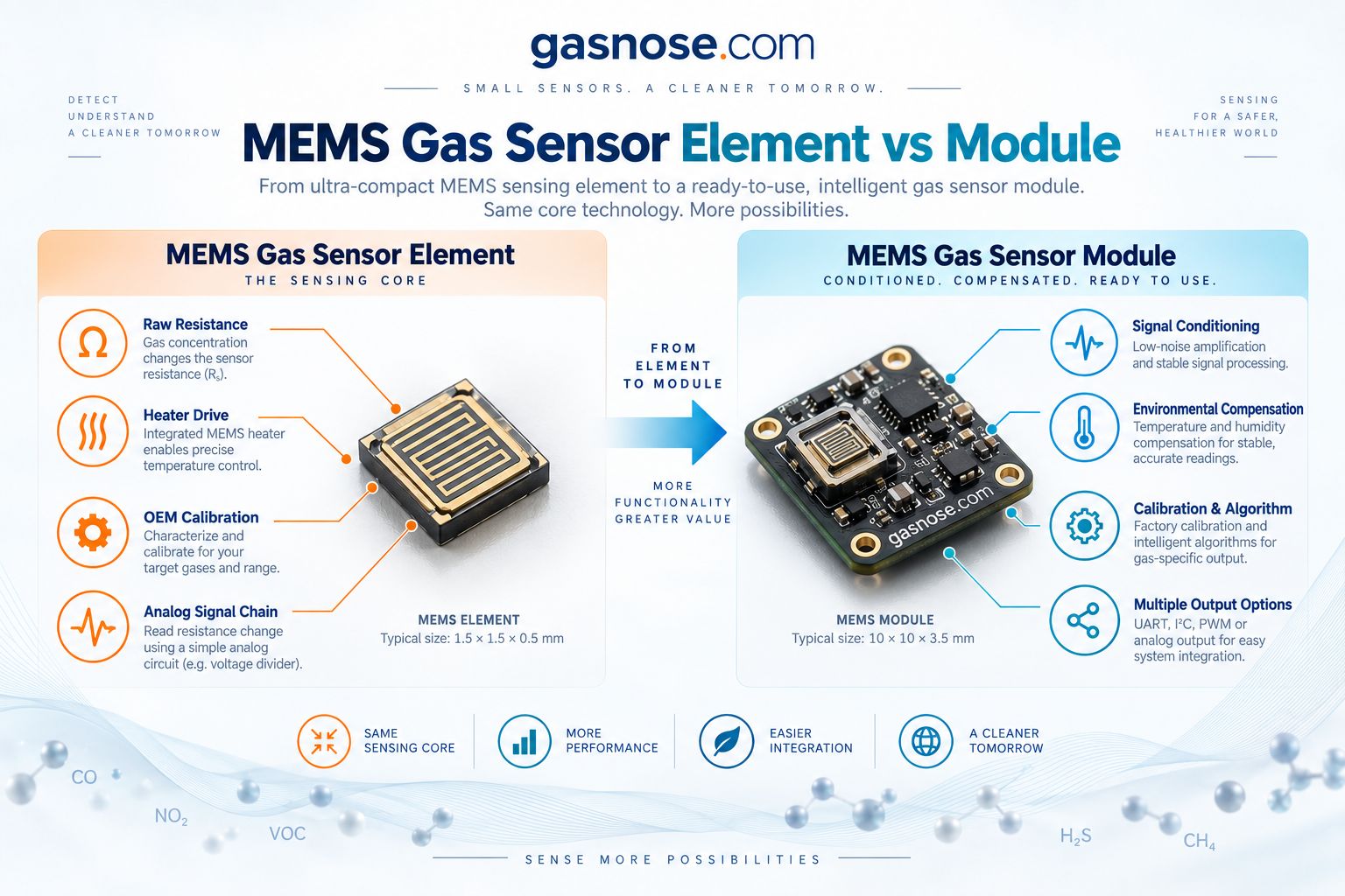
MEMS gas sensing products exist at very different integration levels. That changes the amount of engineering work left to the OEM.
Raw MEMS element
- Resistance or conductance output
- Heater drive required
- Analog front-end required
- OEM calibration required
- Maximum design flexibility
Conditioned module
- Signal conditioning
- Temperature/RH compensation
- Factory calibration or algorithm
- UART / I²C / PWM / analog outputs
- Lower integration burden
For a broader integration framework, see Sensor Element vs Sensor Module.
Electronic nose
MEMS sensor arrays + AI: how an electronic nose works
Typical electronic-nose pipeline
- MEMS sensor array: multiple sensing materials or temperature conditions create complementary responses.
- Response pattern: time-series and channel-specific resistance curves are collected.
- Feature extraction: peak, slope, area, time constants and channel ratios are calculated.
- Model training: labeled samples teach the model to separate known classes.
- Classification: the system outputs the most likely gas, odor or operating state.

Selection workflow
How to choose a MEMS gas sensor
1. Define the target
Identify the gas or odor family, required range and whether the goal is alarm, trend, ppm measurement or classification.
2. Define the power model
Check continuous, duty-cycled and heater-profile power rather than relying on one headline number.
3. Define the environment
Temperature, humidity, siloxanes, VOC background, airflow and enclosure materials can change field performance.
4. Define the integration level
Choose between raw MEMS element, conditioned module or multi-channel intelligent subsystem.
Before design freeze
- Target gas and interferents
- Required concentration range
- Single-temperature or temperature-cycled operation
- Continuous or duty-cycled power budget
- Ambient temperature and RH range
- Warm-up and response-time requirement
- Analog vs digital interface
- Production calibration and field validation plan
MEMS OEM checklist
Record the complete sensing task rather than choosing by gas name alone.
- Alarm / trend / quantitative / classification objective
- Likely VOC and chemical background
- Enclosure and airflow design
- Allowed heater power and thermal rise
- Calibration ownership
- Temperature/RH compensation strategy
- Contamination exposure
- Expected lifetime and drift strategy
Useful Gas Nose tools: Gas Sensor Product Finder and Gas Concentration Converter.
Representative OEM implementations
MEMS gas sensor examples
These examples show how MEMS technology is used for combustible gases, VOCs, oxidizing gases and multi-channel electronic-nose systems.
| Example | Target / role | What it demonstrates | Integration direction |
|---|---|---|---|
| Winsen GM-402B | MEMS combustible gas sensor | Compact micro-hotplate combustible-gas sensing | Raw MEMS element for OEM electronics |
| Winsen GM-502B | MEMS VOC sensor | Low-power MEMS route for VOC / IAQ response | Raw element + OEM calibration |
| Winsen GM-102B | MEMS NO₂ route | Example of MEMS sensing for an oxidizing gas | Application-specific calibration |
| Winsen ZM101-A | Multi-channel AI Nose | MEMS sensor array + environmental compensation + AI integration | Smart electronic-nose subsystem |
FAQ
MEMS gas sensor FAQ
What does MEMS mean in gas sensors?
MEMS stands for Micro-Electro-Mechanical Systems. In gas sensing, it usually refers to a microfabricated structure that integrates a tiny heater, sensing film and electrodes on a thermally isolated chip.
How does a MEMS gas sensor work?
In a typical MEMS MOX sensor, a micro-hotplate heats the gas-sensitive film. Gas molecules interact with the heated surface and change the film’s electrical resistance or conductivity. Electronics then measure and process that response.
Why do MEMS gas sensors use a micro-hotplate?
The micro-hotplate heats only a very small active region. This lowers thermal mass and makes it possible to reduce heater energy, reach operating temperature quickly and switch between temperature setpoints.
Are MEMS gas sensors always metal-oxide sensors?
No. MEMS describes the device architecture, not the chemistry. Many compact MEMS gas sensors use MOX materials, but MEMS structures can support other sensing mechanisms as well.
What is the difference between traditional MOS and MEMS MOX?
Traditional MOS sensors often heat a larger ceramic or planar structure. MEMS MOX sensors use a micro-hotplate with lower thermal mass, enabling smaller packages, faster thermal control and lower heater power.
Why is temperature cycling useful in MEMS gas sensors?
Different gases and surface reactions respond differently as temperature changes. Cycling the heater through multiple temperatures creates a richer response pattern that can improve gas discrimination.
Can a MEMS gas sensor identify one gas selectively?
Not automatically. Many MEMS MOX sensors remain broadband-sensitive. Selectivity depends on sensing material, heater profile, filters, calibration and algorithms.
Are MEMS gas sensors suitable for battery-powered devices?
They can be, especially when the micro-hotplate is operated with an optimized duty cycle. Total system power must still include the heater profile, electronics, MCU, communications and sampling strategy.
What gases can MEMS gas sensors detect?
Depending on the sensing material, MEMS gas sensors can be designed for VOCs, combustible gases, hydrogen, carbon monoxide, nitrogen dioxide, ammonia, hydrogen sulfide and other target families. The exact target must be verified for the individual sensor.
How does AI work with MEMS gas sensors?
AI analyzes response fingerprints from multiple sensor channels, heater temperatures or time-series features. It classifies patterns produced by the physical sensors; it does not replace the sensing chemistry.
Need to choose a MEMS gas sensing architecture?
Start with the real sensing task: target gas, range, cross-sensitivity, power budget, heater strategy, environmental conditions and required integration level. MEMS is most valuable when micro-scale thermal control solves a real system problem—not simply because the sensor package is smaller.