




A gas sensor may provide an accurate reading when it is first installed, but that does not guarantee that it will deliver the same measurement performance months or years later. Its sensing material, electrodes, optical components, electronics, and sampling path can change with operating time and exposure conditions. As a result, the sensor’s zero point, sensitivity, or overall measurement response may gradually change.
This is where gas sensor stability and gas sensor drift become important.
Stability describes the ability of a measuring instrument to maintain its metrological characteristics over time under specified conditions. Drift describes a change in an instrument’s indication or measurement characteristics over time. In practical gas detection, drift is one of the effects engineers monitor when evaluating long-term stability.
The two terms are closely related, but they are not interchangeable. A stability evaluation asks whether the sensor continues to meet its performance requirements over a defined period. A drift evaluation measures how much a particular output or characteristic has changed.
This distinction matters when selecting gas sensors, designing calibration procedures, validating gas detectors, and planning maintenance for industrial safety systems, environmental monitoring equipment, and process analyzers.
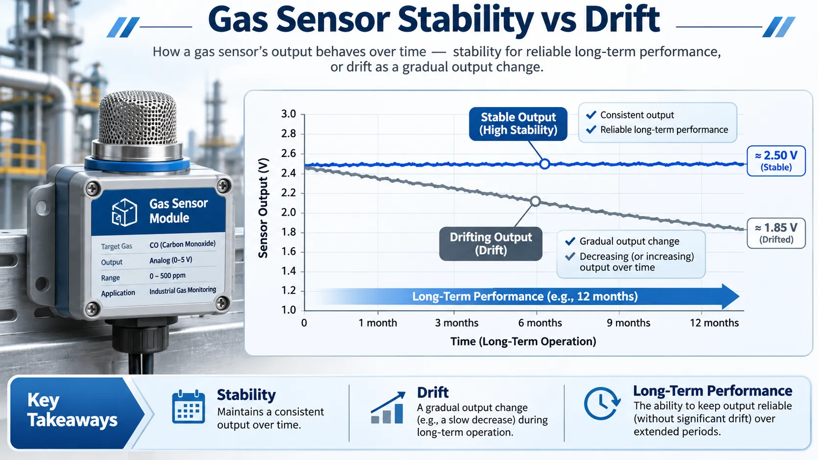
Gas sensor stability concerns the ability to maintain measurement performance over time, while drift describes a change in output or measurement characteristics. The curves are conceptual examples, not specifications for a particular sensor.
1. What Is Gas Sensor Stability?
Gas sensor stability is the ability of a sensor or measuring instrument to maintain its metrological characteristics over time under specified operating conditions.
Depending on the sensor and application, the characteristics being evaluated may include:
- Zero-point output or baseline.
- Sensitivity to the target gas.
- Measurement bias and accuracy.
- Repeatability under defined conditions.
- Response characteristics across the measurement range.
- Performance under specified temperature, humidity, and pressure conditions.
A sensor is considered stable when these characteristics remain within the applicable limits over the evaluation period. Stability does not necessarily mean that the output is perfectly constant. Real sensors have noise, measurement uncertainty, environmental dependencies, and finite tolerances.
For example, a gas transmitter exposed to a constant reference-gas concentration may show small short-term fluctuations while its average output remains within a defined tolerance over several months. That may be acceptable stability for the intended application.
The acceptable level of stability depends on the measurement purpose. A process-control analyzer, a low-level toxic-gas detector, and a residential gas alarm may have different performance requirements and verification procedures.
Stability is a performance characteristic, not a single universal number
A datasheet may state a zero-drift limit, a span-drift limit, or a long-term stability specification. These values describe particular characteristics under stated conditions. They should not automatically be treated as a complete measure of the sensor’s overall stability.
When reviewing a specification, check:
- Which characteristic is being evaluated.
- Whether the value is expressed per day, month, or year.
- Whether the value is an absolute change or a percentage of full scale.
- The temperature, humidity, pressure, and gas conditions.
- Whether the specification applies to the sensing element, transmitter, or complete detector.
- The test duration and measurement method.
A statement such as “long-term stability: ±2% FS per year” is meaningful only when the manufacturer defines the test conditions and the meaning of the stated full-scale range.
2. What Is Gas Sensor Drift?
Gas sensor drift is a change in sensor indication or measurement characteristics over time that is not caused by a change in the gas concentration being measured.
In a practical test, an engineer may expose a sensor to the same reference-gas concentration at different times. If the output changes beyond the expected measurement variation, the result may indicate drift.
Drift can affect different parts of the measurement response:
- Zero drift: A change in the output when the sensor is exposed to zero gas or its defined baseline condition.
- Span drift: A change in sensitivity or response at a specified calibration-gas concentration.
- Baseline drift: A gradual change in the sensor’s baseline output.
- Sensitivity drift: A change in the relationship between gas concentration and sensor output.
The exact terminology and calculation can vary by sensor design and manufacturer. A test report should state what was measured rather than relying on a label alone.
For a more detailed explanation of the different drift mechanisms and their measurement, see What Is Gas Sensor Drift? Zero Drift, Span Drift & Baseline Drift Explained.
Drift is not always caused by the sensing element
The measured output of a gas detection system can be affected by more than the sensing element itself. Changes in the transmitter electronics, sampling pump, tubing, filters, optical chamber, power supply, or signal-processing configuration can also change the indicated result.
Environmental conditions may produce a reversible output change rather than permanent drift. For example, a temperature change can alter a sensor’s response. If the output returns to its previous value when temperature returns to the original condition, the effect should not automatically be described as irreversible aging.
A sound stability test therefore controls or records relevant influence quantities and evaluates the complete measurement chain.
3. Gas Sensor Stability vs Drift: Key Differences
Stability and drift describe different aspects of long-term measurement performance.
| Comparison | Gas sensor stability | Gas sensor drift |
|---|---|---|
| Meaning | Ability to maintain metrological characteristics over time | Change in indication or measurement characteristics over time |
| Nature | A performance characteristic | An observed change |
| Main question | Does the sensor continue to meet its performance requirements? | How much has the measured characteristic changed? |
| Evaluation | Assess performance against defined limits over a period | Compare measurements made at different times |
| Typical evidence | Stability test results and performance history | Zero shift, span change, bias change, or drift rate |
| Engineering use | Sensor selection, qualification, and lifecycle evaluation | Calibration decisions, fault investigation, and trend monitoring |
The relationship can be summarized simply:
- Stability describes how well measurement performance is maintained.
- Drift describes a change that can reduce or otherwise affect that stability.
- Drift data can be used to evaluate whether a sensor remains within its required stability limits.
A sensor may show measurable drift and still be suitable for an application if the change remains within the permitted performance limits and the detector is maintained according to its requirements. Conversely, a small drift may be unacceptable in an application with very tight measurement tolerances.
Stability does not mean zero drift
No practical measurement system should be assumed to have absolutely zero drift under all conditions and throughout its entire service life.
A more useful engineering question is whether the sensor’s drift remains sufficiently small, predictable, and manageable for the intended application. This requires a defined measurement range, operating environment, time period, and acceptance criterion.
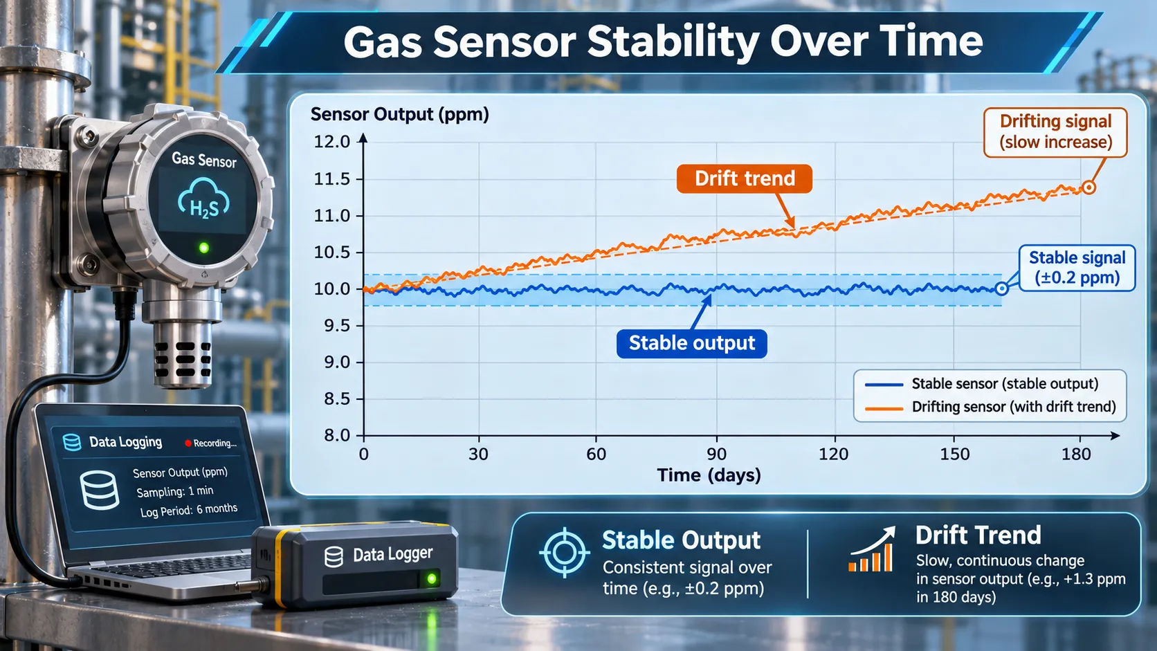
Conceptual comparison of a sensor whose output remains within a narrow band and one whose output gradually changes over time. Actual stability limits must come from the applicable product specification or test requirement.
4. Types of Gas Sensor Stability
Stability can be evaluated over different time periods and for different measurement characteristics. The following categories are useful when planning tests and reviewing datasheets.
Short-term stability
Short-term stability describes how consistently a sensor maintains its output over a relatively short, defined period under controlled conditions.
A short-term evaluation may involve repeated exposure to zero gas and one or more target-gas concentrations. Engineers monitor the output for fluctuations, baseline changes, and variation between repeated exposure cycles.
Short-term stability testing is useful during:
- Initial sensor characterization.
- Production quality control.
- Design verification.
- Evaluation of warm-up and conditioning behavior.
- Comparison of sensor samples under the same test conditions.
Short-term stability should not be confused with repeatability. Repeatability concerns agreement between repeated measurements under specified conditions. A short-term stability test examines whether relevant measurement characteristics remain consistent throughout a defined period.
Long-term stability
Long-term stability describes the ability to maintain measurement performance over extended operation.
The evaluation period may be weeks, months, or longer, depending on the application and product requirements. Measurements are repeated at defined intervals to identify changes in zero, sensitivity, bias, or other performance characteristics.
Long-term stability is particularly important for:
- Fixed industrial gas detectors.
- Continuous emissions and environmental monitoring.
- Process analyzers.
- Remote monitoring stations.
- Equipment where frequent manual calibration is difficult.
Long-term results should include the test conditions and the maintenance or calibration actions performed during the evaluation. A sensor that has been recalibrated during the test cannot be assessed in the same way as a sensor operating without adjustment.
Zero-point stability
Zero-point stability describes how well the sensor maintains its output under a defined zero-gas or baseline condition.
A changing zero output can create an offset across the measurement range. The effect may be particularly important when measuring low gas concentrations, where a small baseline change can represent a substantial proportion of the measured value.
Span or sensitivity stability
Span stability describes how well the sensor maintains its response to a known target-gas concentration.
A sensor may retain a similar zero output while its sensitivity changes. In that case, the output at the calibration-gas concentration may move even though the baseline appears stable.
Environmental stability
Environmental stability describes how well the sensor maintains its specified performance when exposed to defined environmental conditions or changes in those conditions.
Temperature, humidity, pressure, vibration, and other application-specific factors may influence the output. Environmental testing should distinguish reversible environmental response from time-dependent changes that remain after the sensor returns to reference conditions.
See How Temperature Affects Gas Sensor Readings and How Humidity Affects Gas Sensors.
5. What Causes Gas Sensor Drift and Reduced Stability?
Gas sensor drift can result from gradual changes in the sensing element, electronics, or gas sampling system. The dominant mechanism depends on the sensing technology, target gas, operating environment, and exposure history.
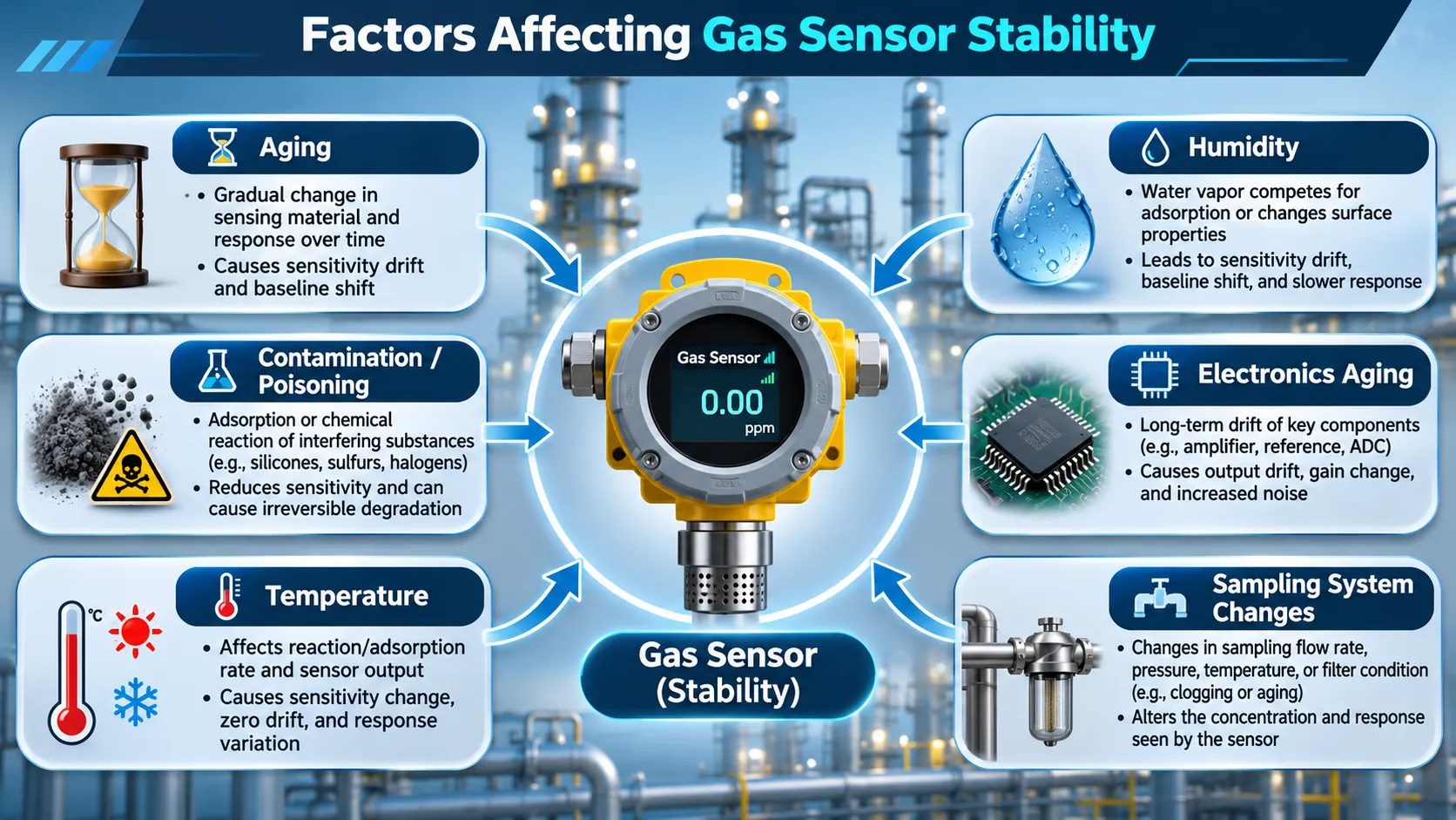
Potential contributors to changing gas sensor performance include aging, contamination, temperature, humidity, electronic component changes, and sampling-system conditions. Their effects are sensor-specific.
Sensor aging
Sensing materials and components can change during prolonged operation. Examples include changes in electrode activity, electrolyte condition, catalyst properties, semiconductor surface characteristics, optical components, or other materials used in the sensing assembly.
Aging may affect baseline output, sensitivity, response time, recovery, or noise. The way these characteristics change depends on the sensor design and operating conditions.
Chemical poisoning and contamination
Certain gases, vapors, aerosols, and contaminants can interfere with or damage sensing materials.
For example, some substances may inhibit catalytic activity, affect electrochemical electrodes, contaminate optical surfaces, or change the behavior of semiconductor sensing materials. The effect may be reversible, partially reversible, or permanent depending on the exposure and sensor technology.
See Gas Sensor Poisoning vs Cross-Sensitivity for the difference between poisoning and responses to interfering gases.
Temperature changes
Temperature can affect reaction rates, gas diffusion, adsorption and desorption, electronic characteristics, and the physical properties of sensor materials.
A temperature-related output change is not automatically permanent drift. Engineers should compare readings at controlled reference conditions or use a validated temperature-compensation method to separate environmental response from longer-term change.
Humidity changes
Water vapor can affect electrolyte systems, surface adsorption, gas transport, and the response of some sensing materials. Condensation or prolonged exposure to unsuitable humidity conditions may also affect the sensor or sampling system.
Humidity should be controlled or recorded during stability tests, particularly when comparing results collected on different dates.
Electronic component aging
The signal-conditioning circuit, amplifier, reference voltage, analog-to-digital converter, power supply, and other electronic components can contribute to changes in the complete detector’s output.
A sensor element may remain relatively stable while the transmitter or measurement electronics introduce offset or gain changes. For this reason, system-level stability testing should evaluate the complete measurement chain.
Sampling system changes
For pumped or extractive gas detectors, the sample path can influence the measured concentration.
Potential issues include:
- Filter loading or contamination.
- Pump performance changes.
- Leaks in tubing or fittings.
- Changes in flow rate.
- Condensation or liquid accumulation.
- Gas adsorption or retention in sample lines.
- Blocked or damaged filters.
These effects can look like sensor drift if the gas concentration reaching the sensing element is not independently verified.
6. How to Test Gas Sensor Stability
A meaningful stability test compares sensor performance over time using defined gas concentrations and controlled or documented conditions.
The test should identify whether the evaluation applies to the sensing element alone or to the complete detector, including its transmitter and sampling system.
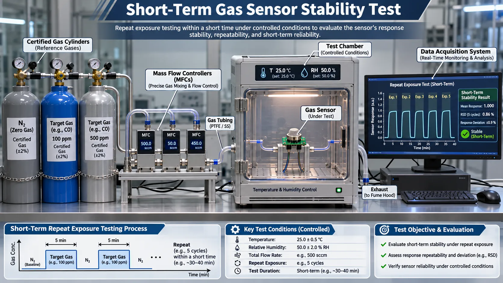
Typical laboratory arrangement for evaluating short-term sensor stability using reference-gas cylinders, mass flow controllers, a test chamber, and a data acquisition system. The exact setup depends on the target gas and test requirements.
Step 1: Define the test objective
Decide which characteristics will be evaluated:
- Zero-point output.
- Span response or sensitivity.
- Measurement bias.
- Repeatability during repeated exposure.
- Response and recovery behavior.
- Output stability over a defined period.
Define the measurement range, target gas, reference concentrations, acceptance limits, and test duration before starting.
Step 2: Prepare the test equipment
A typical laboratory setup may include:
- Certified zero gas and target-gas mixtures.
- Gas regulators and compatible tubing.
- Mass flow controllers or a calibrated gas mixing system.
- A test chamber or suitable gas interface.
- Temperature and humidity monitoring.
- A data acquisition system.
- A reference analyzer where required to verify delivered concentration.
Use gas mixtures and materials compatible with the target gas. Follow the applicable safety procedures for cylinder handling, ventilation, exhaust, and toxic or flammable gases.
Step 3: Condition the sensor
Follow the manufacturer’s instructions for warm-up, stabilization, and conditioning.
Record the sensor’s initial operating conditions, firmware or configuration where relevant, power supply, flow rate, temperature, humidity, and pressure.
For related information, see What Is Gas Sensor Warm-Up Time?.
Step 4: Establish the initial zero response
Apply the specified zero gas or background gas and allow the output to reach the defined measurement condition.
Record the initial zero output, including the measurement unit and the averaging or stabilization method used.
Step 5: Establish the initial span response
Apply one or more known target-gas concentrations across the intended measurement range.
Record the sensor output at each concentration. If the sensor uses a nonlinear response or multiple calibration points, retain the full response data rather than relying on a single span point.
Step 6: Repeat measurements at defined intervals
Repeat the zero and span measurements according to the test schedule.
For example, a development program may collect data at the start of testing and then after selected intervals such as one day, one week, one month, three months, six months, and twelve months. These are illustrative checkpoints, not a universal test schedule or regulatory requirement.
Keep the gas delivery, flow, exposure time, stabilization criterion, and environmental conditions comparable.
Step 7: Compare the results
Compare the initial and later measurements for:
- Zero-point change.
- Span response change.
- Sensitivity change.
- Bias at each test concentration.
- Repeatability within each test session.
- Any changes in response or recovery behavior.
Plotting the results over time makes gradual changes easier to identify.
Step 8: Document calibration and maintenance
Record every calibration, adjustment, sensor replacement, filter change, or repair performed during the test.
A calibration adjustment changes the instrument’s measurement response. The data before and after adjustment should be clearly distinguished so that the original drift behavior is not hidden.
Short-term and long-term testing answer different questions
Short-term tests help establish whether the sensor behaves consistently during repeated measurements under controlled conditions. Long-term tests help determine whether important measurement characteristics remain within requirements as the sensor ages and operates.
Neither test replaces the other. A sensor may perform consistently over several hours but still experience significant changes after months of operation.
7. How to Calculate Gas Sensor Drift Rate
Drift can be expressed as an absolute change, a relative change, or a rate of change over time. The correct method depends on the measured characteristic and the manufacturer’s specification.
Absolute drift
The absolute change in output between two measurement times can be calculated as:
[
D_{\mathrm{abs}}=Y_t-Y_0
]
Where:
- (Y_0) is the initial output.
- (Y_t) is the output at the later measurement time.
- (D_{\mathrm{abs}}) is the absolute output change.
For example, if a detector indicates 0.20 ppm under a defined reference condition at the beginning of a test and 0.35 ppm after 90 days, the absolute change is:
[
D_{\mathrm{abs}}=0.35-0.20=0.15\ \mathrm{ppm}
]
This example illustrates the calculation only. It is not a performance specification or acceptable drift limit.
Relative drift
Relative drift expresses the output change as a percentage of the initial output:
[
D_{\mathrm{rel}}=
\frac{Y_t-Y_0}{Y_0}\times100%
]
This calculation is useful only when the initial value is a suitable non-zero reference. It can become misleading or undefined when the initial output is zero or very close to zero.
For zero-point drift, percentage of initial output is often not the most useful normalization method.
Drift rate over time
A simple average drift rate can be calculated as:
[
R_D=\frac{Y_t-Y_0}{t-t_0}
]
The result may be expressed in ppm/day, ppm/month, mV/month, or another unit appropriate to the measured output.
For example, if the output changes by 0.15 ppm over 90 days:
[
R_D=\frac{0.15}{90}=0.00167\ \mathrm{ppm/day}
]
This is an average rate over the test period. It does not prove that the drift occurred at a constant rate.
Drift as a percentage of full scale
When the output is normalized to the full-scale span, the calculation can be expressed as:
[
D_{\mathrm{FS}}=
\frac{|Y_t-Y_0|}{Y_{\mathrm{FS}}}\times100%
]
Where (Y_{\mathrm{FS}}) is the defined full-scale output span or measurement span, according to the applicable specification.
If the datasheet states drift as a percentage of full scale per month or per year, use the manufacturer’s stated definition of full scale. Do not assume that all manufacturers use the same normalization.
Zero drift and span drift require separate evaluation
For a simplified linear response model:
[
Y=a+bC
]
Where:
- (Y) is the sensor output.
- (C) is the target-gas concentration.
- (a) is the zero offset.
- (b) is the sensitivity or slope.
A change in (a) represents a zero-offset change. A change in (b) represents a sensitivity or span change.
A sensor can therefore maintain its zero output while its sensitivity changes, or maintain its sensitivity while its baseline shifts. Measuring only one point may not reveal both effects.
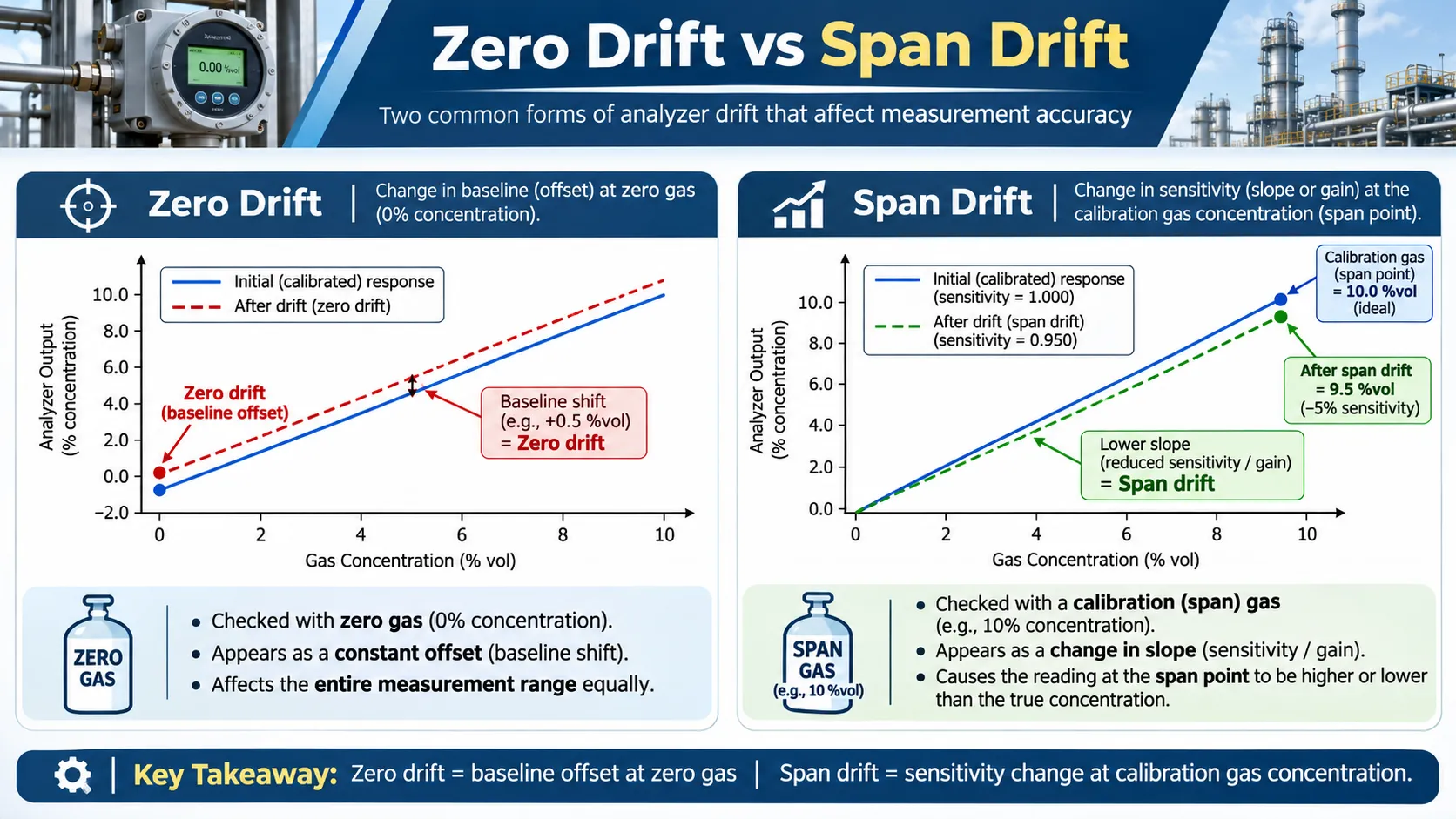
Conceptual response curves showing zero drift as a change in baseline offset and span drift as a change in response slope. Actual sensor calibration models may be nonlinear and require more than two points.
For a deeper explanation, see What Is Gas Sensor Drift?.
8. Stability Considerations by Gas Sensor Technology
Different sensing technologies have different materials, operating principles, and failure mechanisms. Stability should therefore be evaluated for the specific sensor model and target gas rather than inferred from the technology name alone.
| Sensor technology | Potential stability considerations | Engineering checks |
|---|---|---|
| Electrochemical | Electrode condition, electrolyte changes, bias history, contamination, and storage conditions | Zero response, span response, conditioning, and manufacturer-recommended operating conditions |
| MOS / semiconductor | Sensing-material aging, surface contamination, heater operation, and humidity effects | Heater control, baseline trend, sensitivity, and environmental compensation |
| NDIR | Optical source and detector characteristics, optical contamination, chamber condition, and temperature effects | Zero and span verification, optical path condition, and reference-channel performance |
| Catalytic bead | Catalyst condition, poisoning, thermal behavior, and exposure history | Response to reference gas, sensor condition, and protection from known contaminants |
| PID | UV lamp condition, electrode contamination, sample-path effects, and humidity | Lamp inspection, baseline, response verification, and sample-system maintenance |
Electrochemical gas sensors
Electrochemical sensors depend on electrode reactions and electrolyte systems. Changes in electrode activity, electrolyte condition, contamination, or operating history may affect the baseline and sensitivity.
The test procedure should follow the manufacturer’s requirements for bias, conditioning, storage, and calibration.
MOS and semiconductor gas sensors
Metal-oxide semiconductor sensors rely on changes in electrical properties associated with gas interactions at the sensing surface. Heater conditions, surface contamination, aging, and environmental influences can affect the response.
Long-term evaluation should monitor baseline resistance or output, sensitivity, heater operation, and the effect of temperature and humidity.
NDIR gas sensors
NDIR sensors measure gas absorption at selected infrared wavelengths. Stability considerations may include the infrared source, detector, optical surfaces, chamber condition, and compensation system.
A change in optical transmission or reference-channel behavior can affect the indicated concentration. Zero and span verification should evaluate the complete optical measurement system.
Catalytic bead sensors
Catalytic bead sensors rely on catalytic oxidation and the associated thermal response. Catalyst condition, contamination, operating temperature, and exposure history may affect sensitivity.
Some contaminants can inhibit catalytic activity. Where poisoning is suspected, a simple zero check may not be sufficient to confirm that the sensor still responds correctly to the target gas.
PID sensors
Photoionization detectors use ultraviolet radiation to ionize compounds with suitable ionization potentials. Lamp condition, electrode cleanliness, humidity, and sample delivery can influence instrument performance.
Maintenance and stability checks should follow the manufacturer’s procedures and should include response verification with an appropriate reference gas.
9. How to Improve Gas Sensor Long-Term Stability
There is no single method that eliminates drift across all gas sensor technologies. The most effective approach is to identify the source of the change and apply controls appropriate to the sensor and application.
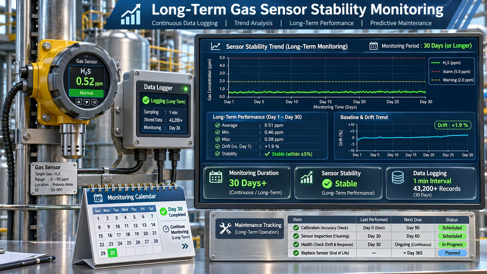
Long-term monitoring combines sensor output records, trend analysis, verification measurements, and maintenance history. The displayed values are illustrative rather than product specifications.
Select a sensor suitable for the operating environment
Review the manufacturer’s operating limits, target-gas compatibility, expected service conditions, and stability specifications.
Consider potential interfering gases, contaminants, temperature and humidity extremes, vibration, pressure, and the availability of maintenance access.
Protect the sensing element
Use appropriate filters, sample conditioning, protective enclosures, and installation practices where required by the application.
Protection must not restrict gas diffusion or introduce unacceptable response delays. The selected filter or sampling arrangement should be validated with the complete detector.
Maintain consistent operating conditions
Operate the sensor within its specified temperature, humidity, pressure, power, and flow conditions.
Where environmental changes are unavoidable, use only compensation methods validated for the sensor model and operating range.
Use a defined calibration and verification procedure
A suitable calibration procedure should specify:
- The zero-gas condition.
- The calibration-gas identity and concentration.
- Gas flow and application method.
- Stabilization criteria.
- Calibration and adjustment steps.
- Acceptance limits.
- Required records.
A calibration adjustment can restore the indicated response at the calibration points, but it does not necessarily reverse material aging or restore the original sensor condition.
Monitor trends rather than isolated readings
Keep records of zero checks, span checks, calibration results, fault events, environmental conditions, and maintenance.
A trend chart can help identify gradual changes that may not be obvious from a single verification. It can also help distinguish a one-time abnormal result from a persistent change.
Replace sensors when performance is no longer acceptable
If a sensor cannot meet the required performance after the manufacturer’s approved maintenance and calibration procedures, it may need replacement.
Replacement decisions should be based on the applicable product instructions, test results, application risk, and relevant safety requirements.
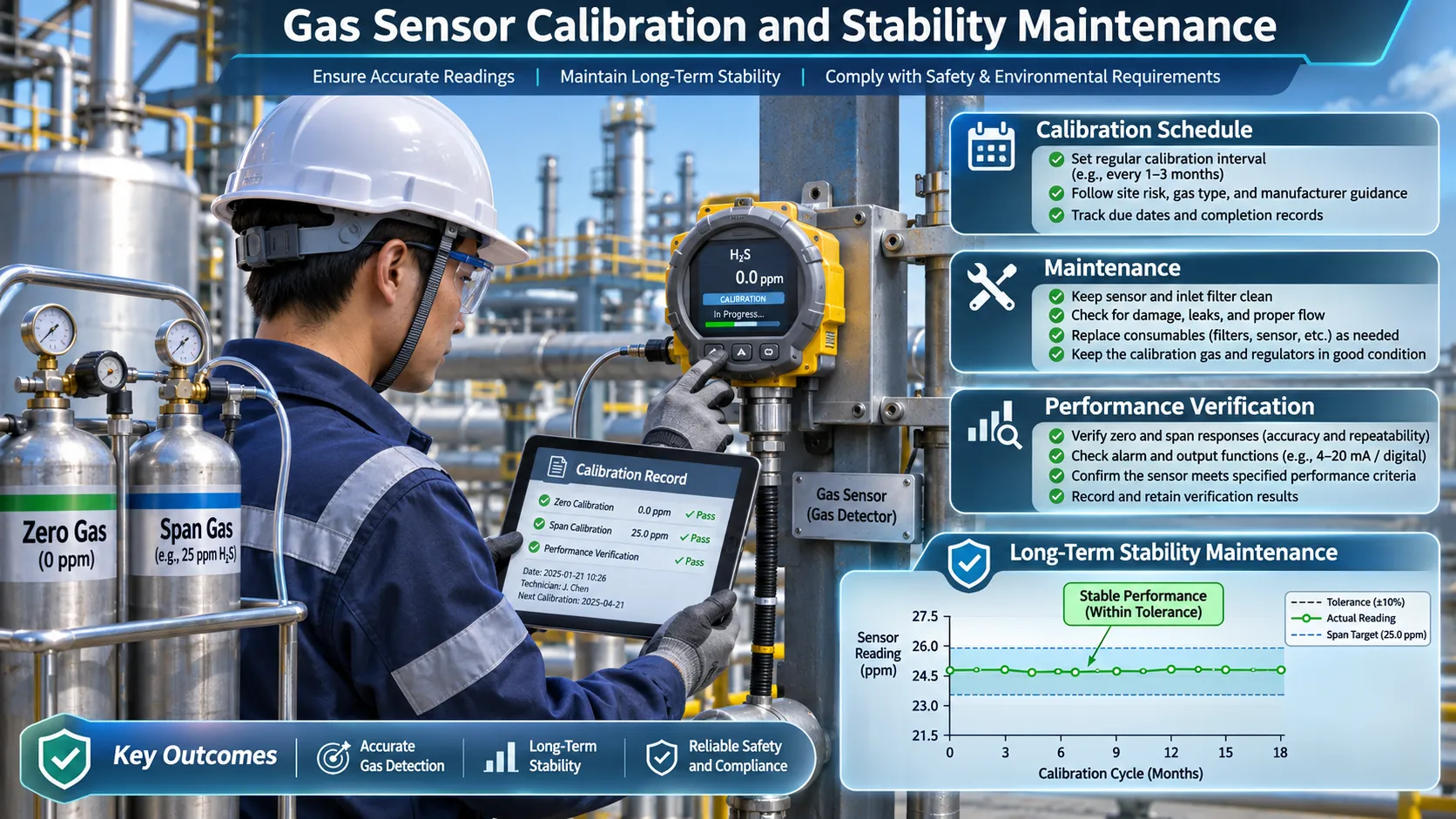
Calibration, maintenance, and performance verification help determine whether a gas detector continues to meet its requirements. The appropriate schedule depends on the sensor, application, manufacturer guidance, and documented performance.
10. How Often Should Gas Sensors Be Calibrated?
There is no single calibration interval suitable for every gas sensor.
The appropriate interval depends on the sensor model, target gas, application risk, operating environment, manufacturer’s instructions, applicable regulations or standards, and the sensor’s observed performance history.
A practical calibration program should consider:
- Manufacturer-recommended calibration and bump-test procedures.
- The consequences of an undetected measurement error.
- Historical zero and span drift.
- Exposure to contaminants or interfering gases.
- Temperature, humidity, and other operating conditions.
- The stability of the gas delivery and sampling system.
- Results from routine inspections and functional checks.
Calibration is not the same as a bump test
A bump test is generally a functional check used to confirm that gas can reach the detector and that the instrument responds as expected. It does not necessarily establish measurement accuracy.
Calibration uses a known reference condition or gas concentration to verify and, where required, adjust the instrument’s response.
Follow the detector manufacturer’s instructions and the requirements applicable to the installation. Do not extend a calibration interval solely because a sensor has performed well in a limited number of checks.
For additional guidance, consult the OSHA Technical Manual guidance on direct-reading instruments.
11. Common Mistakes When Evaluating Gas Sensor Stability
- Treating stability and drift as synonyms. Stability is a performance characteristic; drift is a change in measurement indication or characteristics over time.
- Checking only the zero point. A sensor may maintain its baseline while its sensitivity changes.
- Using only one calibration concentration. A single point may not reveal changes in slope or nonlinear response.
- Confusing repeatability with long-term stability. Good repeatability during one test session does not prove that performance will remain unchanged for months.
- Ignoring environmental conditions. Temperature, humidity, pressure, and flow changes can influence the result.
- Failing to verify the gas delivery system. Leaks, blocked filters, pump changes, and sample-line effects can look like sensor drift.
- Comparing measurements made under different conditions. Before-and-after results should use comparable reference gases, flow, stabilization criteria, and environmental conditions.
- Resetting calibration without retaining the original data. Calibration adjustments can hide the amount of drift that occurred before adjustment.
- Assuming a single drift rate applies throughout service life. Drift may be nonlinear, intermittent, or affected by exposure events.
- Using a universal calibration interval. Calibration frequency should be justified by manufacturer guidance, application risk, and documented performance.
12. Frequently Asked Questions
What is gas sensor stability?
Gas sensor stability is the ability of a sensor or measuring instrument to maintain its metrological characteristics over time under specified conditions. Relevant characteristics may include zero output, sensitivity, bias, and response across the measurement range.
What is the difference between gas sensor stability and drift?
Stability describes how well the sensor maintains its measurement performance over time. Drift describes a change in the sensor’s indication or measurement characteristics over time. Drift is one important factor used to evaluate stability.
What causes gas sensor drift?
Possible causes include sensing-material aging, electrode or electrolyte changes, contamination, poisoning, optical-component changes, electronic aging, and changes in the sampling system. Environmental conditions can also influence the output and must be considered during testing.
How is gas sensor stability measured?
Stability is evaluated by measuring selected sensor characteristics at defined times under controlled or documented conditions. Common checks include zero response, span response, sensitivity, and bias using known reference-gas concentrations.
What is long-term stability in gas sensors?
Long-term stability describes the ability to maintain required measurement performance over an extended operating period. It is commonly evaluated through repeated measurements over weeks, months, or longer, depending on the application and test requirements.
What is short-term sensor stability?
Short-term stability describes how consistently a sensor maintains its output or response during a relatively short evaluation period under defined conditions. It is useful for characterization and design verification but does not replace long-term testing.
What is the difference between zero drift and span drift?
Zero drift is a change in output under a defined zero-gas condition. Span drift is a change in sensitivity or response at a known calibration-gas concentration. Both should be evaluated when the application requires reliable measurements across a range.
How often should gas sensors be calibrated?
The interval depends on the sensor model, manufacturer’s instructions, application risk, operating conditions, applicable requirements, and historical performance. A calibration schedule should be supported by documented verification and maintenance data.
Can gas sensor drift be corrected?
Some drift can be corrected through an approved zero or span calibration procedure. However, calibration does not necessarily reverse material degradation, poisoning, or other physical changes. A sensor that cannot meet its performance requirements after approved maintenance may need replacement.
Which gas sensor technology has the best long-term stability?
There is no universal winner. Long-term stability depends on the specific sensor design, target gas, materials, operating environment, electronics, sampling arrangement, and maintenance. Compare model-specific test data under conditions relevant to the intended application.
Conclusion
Gas sensor stability and gas sensor drift are closely related, but they describe different aspects of measurement performance.
Stability is the ability to maintain metrological characteristics over time. Drift is a change in indication or measurement characteristics that may affect that ability. Evaluating both is essential when selecting sensors for long-term monitoring and designing calibration and maintenance programs.
For a reliable engineering evaluation:
- Define which measurement characteristics need to remain stable.
- Test both zero response and span sensitivity.
- Use known reference-gas concentrations.
- Control or record temperature, humidity, pressure, flow, and exposure conditions.
- Repeat measurements at defined intervals.
- Record calibration adjustments and maintenance actions.
- Compare results against the product specification and application requirements.
A sensor should not be judged only by its initial accuracy or a single successful calibration. Its performance over time is what determines whether it can continue to provide reliable gas measurements in the intended application.
References and Further Reading
Metrology and technical references
- BIPM — Joint Committee for Guides in Metrology (JCGM) Publications — International metrology terminology and guidance, including the vocabulary used to describe measurement-instrument characteristics.
- MET4H2 — State of the Art for Sensors in the Hydrogen Industry — Review of sensor technologies and performance characteristics relevant to hydrogen applications.
- NREL — Standard Hydrogen Test Protocols for Sensor Testing — Research resources and test-protocol information for hydrogen sensor evaluation.
- OSHA — Technical Manual: Direct-Reading Instruments — Guidance on the use and evaluation of direct-reading instruments in occupational settings.
Related GasNose articles
- What Is Gas Sensor Drift? Zero Drift, Span Drift & Baseline Drift Explained
- Gas Sensor Hysteresis Explained
- Gas Sensor Repeatability vs Accuracy: What’s the Difference?
- What Is Gas Sensor Warm-Up Time?
- How Temperature Affects Gas Sensor Readings
- How Humidity Affects Gas Sensors
- Gas Sensor Poisoning vs Cross-Sensitivity
- Gas Sensor Detection Limit: LOD vs Resolution vs Accuracy
