



An electrochemical gas sensor is often described as producing a current proportional to gas concentration.
That leads to an obvious question:
If there is no target gas, shouldn’t the sensor current be exactly zero?
Not necessarily.
A real electrochemical gas sensor can produce a small baseline output even when no target gas is intentionally present. In datasheets, this is commonly called zero current or described as a zero-air equivalent output.
The simplest definition is:
Zero current is the sensor output measured under the manufacturer’s specified zero-gas conditions before adding the target-gas response.
It is important because the target-gas signal may be very small, especially in low-ppm or ppb applications.
A useful simplified model is:
Measured sensor current
=
Zero / baseline current
+
Target-gas-induced current
+
Short-term noise and other response components
The zero-current term is a baseline offset. It is not the same as zero drift, sensor noise, zero bias or cross-sensitivity.
Zero Current: Quick Definition
| Term | What It Describes |
|---|---|
| Zero Current | Baseline sensor output under specified zero-target-gas conditions |
| Target-Gas Current | Additional electrochemical current associated with target gas |
| Zero Drift | Change in the zero baseline over time |
| Noise | Short-term random fluctuation around the baseline |
| Zero Bias | A sensor operating condition in which no intentional potential difference is applied between working and reference electrodes |
The most useful distinction is:
Zero current is a value. Zero drift is a change in that value over time. Noise is the short-term fluctuation around it. Zero bias describes electrode potential—not output current.
How Does an Electrochemical Gas Sensor Produce Current?
Electrochemical gas sensors commonly use an amperometric measurement principle.
A conventional three-electrode cell contains:
- Working Electrode (WE)
- Reference Electrode (RE)
- Counter Electrode (CE)
Target gas diffuses through the sensor inlet and reaches the working electrode. An oxidation or reduction reaction occurs, and the resulting electrical current is related to the amount of gas reaching the electrode.
The reference electrode helps maintain the working electrode at the required electrochemical potential, while the counter electrode completes the electrochemical reaction path.
A potentiostat and transimpedance amplifier then convert the sensor current into an electrical signal that can be digitized and converted to gas concentration.
For the complete sensor architecture, see Electrochemical Gas Sensors: Working Principle, Advantages, Gases & Selection Guide.
Analog Devices describes the same basic signal chain: the potentiostat maintains the required working/reference-electrode bias, while the current at the sensing electrode is converted by a transimpedance amplifier and ADC into a gas-concentration measurement.
Why Is There Current When No Target Gas Is Present?
Zero air is not the same thing as an ideal electrochemical system with no electrical activity.
A real sensor can have a small background output because of factors such as:
- electrode background reactions
- electrochemical equilibrium
- electrolyte behavior
- trace impurities
- sensor manufacturing variation
- applied operating bias
- temperature
- humidity
- stabilization state
- internal leakage or external readout offset
The dominant cause depends on the sensor chemistry and construction.
That is why the correct engineering statement is:
Zero target gas does not require zero electrical output.
This does not mean a non-zero baseline is automatically acceptable at any magnitude. The expected zero-current range should come from the specific sensor datasheet.
Zero Current and Target-Gas Current
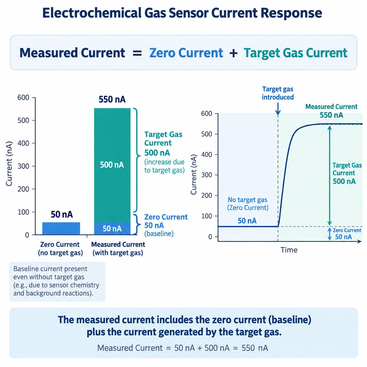
Consider a simplified example.
Suppose a sensor produces:
Zero current = 50 nAThen target gas produces an additional:
Target-gas current = 500 nAThe measured current becomes approximately:
Measured current
= 50 nA + 500 nA
= 550 nA
This is a conceptual model rather than a universal circuit equation. Real instruments may also include:
- electronic offset
- temperature compensation
- auxiliary-electrode correction
- digital filtering
- calibration coefficients
But the model is useful because it shows why the raw sensor output does not necessarily begin at zero.
How Is Zero Current Shown in a Datasheet?
Manufacturers commonly express zero current in one of two ways.
Electrical Current
For example:
Zero current: -80 to +80 nAThis is the raw electrochemical baseline specification.
Gas-Equivalent Concentration
For example:
Zero current: < ±0.4 ppm equivalentThis expresses the same type of baseline offset in terms of the amount of target gas that would create a similar signal.
Alphasense’s current NO₂-A1 datasheet, for example, separately specifies:
- sensitivity
- zero current
- RMS noise / resolution
- range
- zero drift
- sensitivity drift
Its zero current is specified as less than ±0.4 ppm equivalent in zero air, while RMS noise / resolution and long-term zero drift are given separately.
That separation is important:
Zero current, noise and drift are different specifications.
See: Alphasense NO₂-A1 Datasheet
How Do You Convert Zero Current to ppm Equivalent?
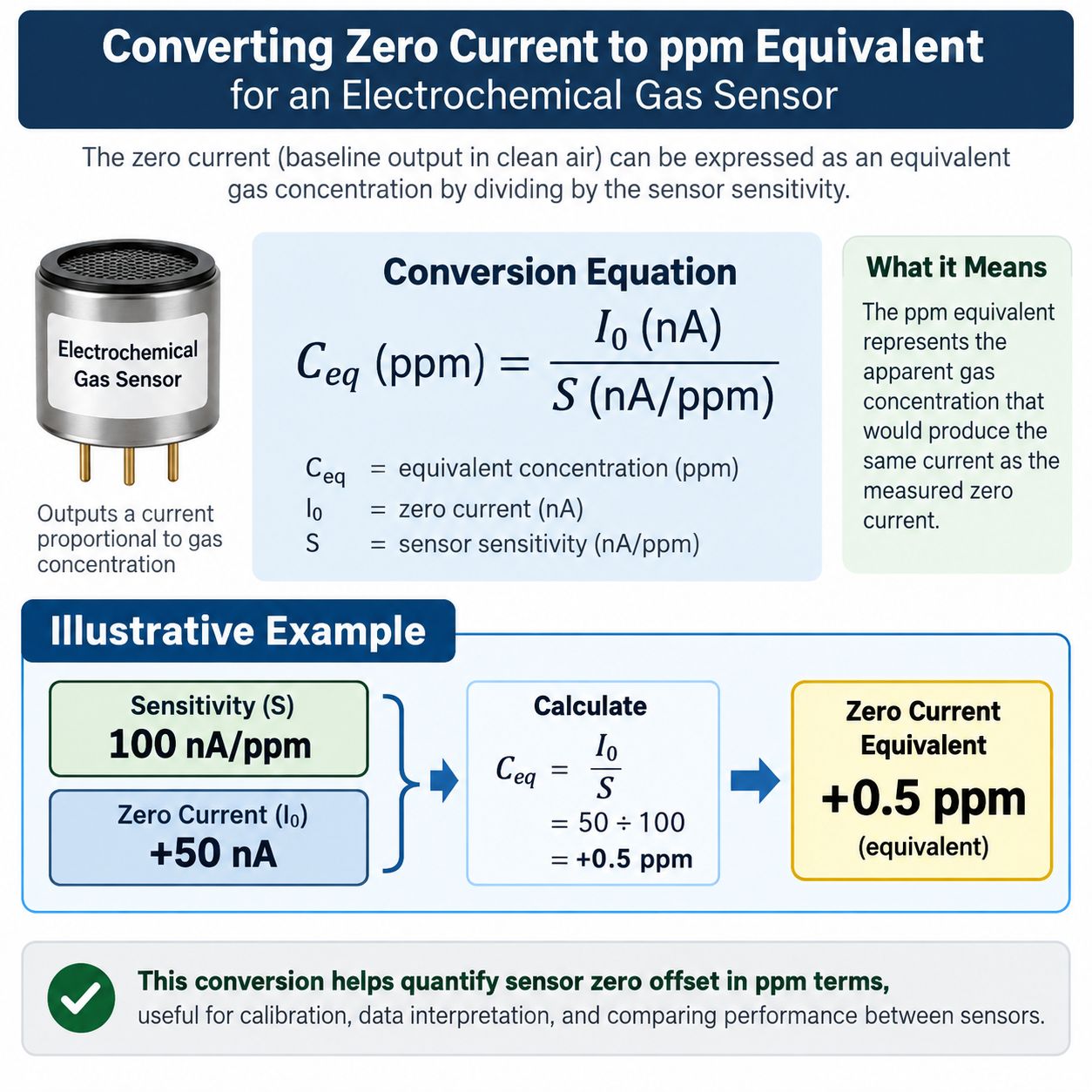
For a sensor with an approximately linear response, a simple conversion is:
Zero-equivalent concentration
=
Zero current
÷
Sensitivity
Suppose:
Sensitivity = 100 nA/ppm
Zero current = +50 nA
Then:
Zero-equivalent concentration
=
50 nA ÷ 100 nA/ppm
=
+0.5 ppm equivalent
This means the baseline current has the same magnitude as the target-gas current that would be expected from approximately 0.5 ppm under the stated sensitivity.
However, this conversion should be used carefully.
It assumes that:
- the sensitivity value applies at the relevant temperature
- the sensor response is sufficiently linear
- current sign conventions are understood
- the zero and sensitivity were determined under compatible conditions
For strongly temperature-dependent or nonlinear systems, the instrument may require additional compensation.
Can Zero Current Be Negative?
Yes.
A datasheet may specify zero current as a positive/negative range such as:
-80 nA to +80 nAor:
< ±0.4 ppm equivalentA negative zero current does not mean there is a physically negative gas concentration.
It means the baseline electrical output lies on the negative side of the defined sensor-current direction.
The instrument may:
- apply a zero offset
- subtract a calibration baseline
- allow a signed engineering value internally
- clamp the user-facing display at zero
depending on the product design.
So:
Negative sensor current and negative gas concentration are not the same concept.
Zero Current vs Zero Bias
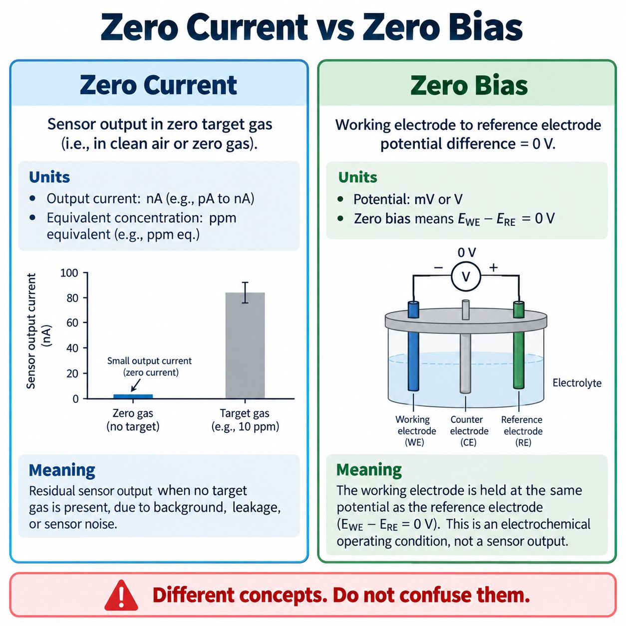
These two terms sound similar but describe completely different things.
Zero Current
Describes:
sensor output under zero-target-gas conditions
Possible units:
- nA
- µA
- ppm equivalent
Zero Bias
Describes:
the electrical potential applied between the working/sensing electrode and the reference electrode
For a zero-bias electrochemical sensor:
WE–RE applied bias = 0 VAnalog Devices explains that in a zero-bias sensor, the working-electrode and reference-electrode control voltages are set to the same potential. Non-zero-bias sensors require a specified potential difference.
See: Analog Devices AN-1563 — Electrochemical Measurements
The key rule is:
A zero-bias sensor can still have non-zero zero current.
Zero bias refers to the operating potential.
Zero current refers to the sensor output.
Why Do Some Electrochemical Sensors Need a Bias Voltage?
The desired electrochemical reaction may require the working electrode to be held at a particular potential relative to the reference electrode.
For example, some nitric oxide sensors require a positive working-electrode bias.
Alphasense currently describes NO sensors that use working-electrode biases such as +200 mV or +300 mV depending on the sensor type.
See: Alphasense Nitric Oxide Sensors
Bias can influence:
- target-gas reaction rate
- sensitivity
- background current
- cross-sensitivity
- response time
- recovery behavior
Therefore:
Zero current must be evaluated at the sensor’s specified operating bias.
For a deeper explanation, see Electrochemical Gas Sensor Bias Voltage Explained.
Zero Current vs Zero Drift vs Noise
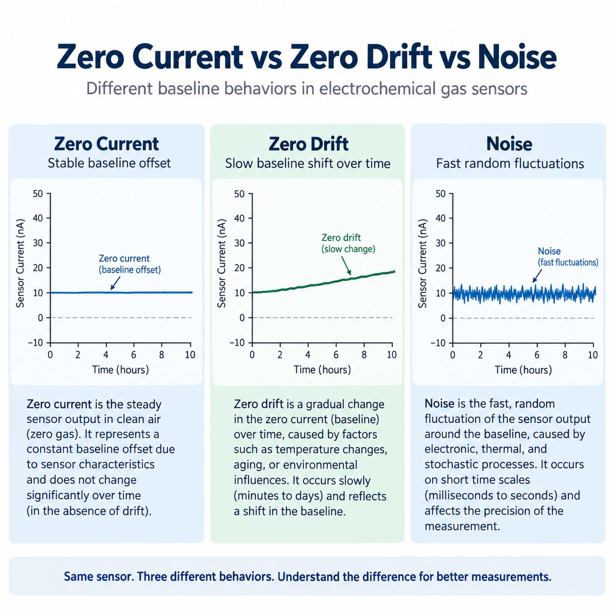
These three concepts are frequently confused.
Zero Current
A baseline value measured at a particular time.
Example:
Zero current = +20 nAZero Drift
A slow change in that baseline over time.
Example:
Month 0: +20 nA
Month 6: +35 nA
Month 12: +50 nA
Noise
Fast random variation around the baseline.
Example:
20
22
19
21
18
23 nA
A concise way to remember the difference is:
Zero current is the offset. Zero drift is the long-term movement of the offset. Noise is the short-term fluctuation around it.
For the long-term behavior, see What Is Gas Sensor Drift? Zero Drift, Span Drift & Baseline Drift Explained.
For low-level measurement, see Gas Sensor Detection Limit: LOD vs Resolution vs Accuracy.
Why Zero Current Matters for Low-Level Measurement
Suppose you are measuring:
50 ppm COA baseline equivalent of:
0.2 ppmmay be relatively small compared with the target signal.
But suppose the application is trying to resolve:
100 ppb NO₂Since:
0.2 ppm = 200 ppbthe baseline behavior can now be larger than the concentration of interest.
This is why low-level electrochemical systems pay close attention to:
- zero current
- RMS noise
- zero drift
- temperature compensation
- humidity effects
- auxiliary-electrode behavior
- analog-front-end noise
At ppb levels, a small baseline problem can become a large measurement problem.
Zero Current Does Not Equal Detection Limit
A sensor can have a non-zero baseline and still achieve a useful detection limit if that baseline is:
- stable
- characterized
- compensated
Likewise, a sensor with a very small mean zero current can still have a poor LOD if the baseline is noisy.
Consider:
Sensor A
Mean zero offset: +0.5 ppm equivalent
Noise: ±0.01 ppm
Sensor B
Mean zero offset: 0 ppm
Noise: ±0.5 ppm
Sensor A has the larger offset.
But Sensor B may be much more difficult to use for trace measurements because the baseline fluctuates strongly.
This is why the useful low-level question is not simply:
How close to zero is the average baseline?
It is:
How stable, predictable and compensatable is the baseline relative to the target signal?
Temperature Can Change Zero Current
Electrochemical sensors are temperature-sensitive systems.
Temperature can affect:
- electrode kinetics
- electrolyte behavior
- gas diffusion
- sensitivity
- zero output
Alphasense states in its current FAQ that both sensitivity and zero current change with ambient temperature.
Its NO₂-A1 datasheet also separately specifies zero shifts at -20°C and 50°C relative to 20°C.
This is why an OEM cannot assume:
Zero current at 20°C
=
Zero current at -20°C
=
Zero current at 50°C
A raw electrochemical cell may require temperature characterization and compensation in the finished detector.
See How Temperature Affects Gas Sensor Readings.
Humidity Can Affect Baseline Behavior
Humidity can affect electrochemical sensing through:
- electrolyte water balance
- membrane behavior
- gas diffusion
- electrode chemistry
- transient environmental response
The effect is sensor-specific.
A zero-current value measured at one humidity condition should not automatically be assumed to apply identically across the full rated humidity range.
For the broader problem, see How Humidity Affects Gas Sensors.
Stabilization Time Matters Before Evaluating Zero
A newly connected electrochemical sensor may not immediately reach a stable baseline.
This is especially important when:
- the sensor has been stored disconnected
- a biased sensor lost its required bias
- the electronics have just powered up
- the environment changed rapidly
Alphasense currently publishes different stabilization times for different toxic-gas sensors. Many CO, H₂S, SO₂, NO₂ and Cl₂ cells require longer stabilization after a long period of removal than after a brief replacement, while biased NO sensors can require much longer stabilization.
Therefore:
Do not judge zero current before the sensor reaches the manufacturer’s specified stabilization condition.
There is no single universal warm-up time for every electrochemical gas sensor.
Zero Current vs Electronic Offset
The detector reading is not produced by the sensor alone.
A typical electrochemical measurement chain includes:
Electrochemical Cell
↓
Potentiostat
↓
Transimpedance Amplifier
↓
ADC
↓
Digital Compensation
↓
Gas Reading
Analog Devices’ CN0425 reference design shows exactly this type of architecture for a three-lead electrochemical gas sensor.
The complete zero reading may therefore contain contributions from:
- sensor zero current
- amplifier offset
- PCB leakage
- ADC offset
- reference drift
- temperature effects
- firmware compensation
If a finished detector shows:
+2 ppmin zero gas, you cannot automatically conclude:
Sensor zero current = +2 ppm equivalentwithout separating the sensor from the rest of the signal chain.
Stable Zero Offset vs Unstable Zero
A stable zero offset can often be characterized and compensated.
An unstable zero is harder.
Sensor A
Zero equivalent:
+0.5 ppm
+0.51 ppm
+0.49 ppm
+0.50 ppm
Sensor B
Zero equivalent:
0 ppm
+0.8 ppm
-0.6 ppm
+0.7 ppm
Sensor A has a larger average offset.
But Sensor B has much worse baseline stability.
For low-level measurement, Sensor A may actually be easier to correct.
So:
A stable offset can often be calibrated. An unstable baseline is much harder to compensate reliably.
Why Four-Electrode Sensors Can Help With Zero Current
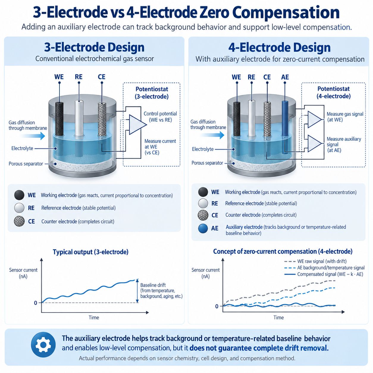
A conventional three-electrode sensor uses:
WE + RE + CESome four-electrode electrochemical sensors add an:
AE = Auxiliary ElectrodeAlphasense states that its A4 and B4 sensors are designed for low-concentration, ppb-level detection and that the fourth auxiliary electrode is used to correct for zero-current changes.
The basic concept is:
Working-electrode signal
=
Target response
+
Background / environmental contribution
while the auxiliary channel provides additional information about:
Background / environmental behaviorThe instrument can then use both channels to improve the final estimate.
However, this should not be simplified into a universal equation such as:
Corrected signal = WE - AEfor every sensor.
Real compensation may depend on:
- sensor-specific coefficients
- temperature
- calibration
- electrode matching
- aging
- manufacturer algorithms
The auxiliary electrode provides additional information, not automatic perfect compensation.
For a full discussion, see 3-Electrode vs 4-Electrode Electrochemical Gas Sensors.
The Fourth Electrode Does Not Always Mean the Same Thing
Not every four-electrode gas sensor uses its fourth electrode for zero-current compensation.
Depending on the sensor, the fourth electrode may be:
- an auxiliary baseline electrode
- a second working electrode
- an interference-compensation electrode
- a diagnostics electrode
Therefore, never infer function from electrode count alone.
Always check the sensor’s:
- pinout
- datasheet
- application note
- readout requirements
Does the Auxiliary Electrode Measure Target Gas?
In an auxiliary-electrode architecture, the AE is intended primarily to provide background or compensation information rather than act as the main target-gas sensing channel.
However, its actual behavior is sensor-specific.
It should not be assumed that:
AE response to target gas = exactly zerounder every condition.
The correct compensation method should come from the sensor manufacturer.
This is particularly important for ppb systems, where even a small mismatch can matter.
Zero Current and Signal-to-Noise Ratio
Zero current itself is not necessarily harmful if it is stable.
The harder problem is when the target-gas signal is similar in magnitude to:
- zero-current variation
- electrical noise
- environmental baseline changes
For example:
Target gas signal = 10 nA
Baseline noise = ±8 nA
is much more difficult than:
Target gas signal = 10 nA
Baseline noise = ±0.5 nA
even if both sensors have the same average zero current.
That is why zero current, RMS noise and sensitivity should be evaluated together.
See Signal-to-Noise Ratio in Gas Sensors: Why SNR Matters.
Zero Current and Cross-Sensitivity
An unexpected baseline reading may not be zero current at all.
Another gas may be present.
If an interferent produces an electrochemical response, the detector can show a non-zero reading even though the target gas is absent.
This is cross-sensitivity, not necessarily zero current.
For example, some CO electrochemical sensors can respond to hydrogen.
The correct troubleshooting question is:
Is the sensor producing a baseline offset, or is it responding to another gas?
See Gas Sensor Cross-Sensitivity Explained.
Zero Current and Calibration
Zero calibration establishes the instrument’s current baseline reference under the required zero-gas condition.
In simple terms:
Measured baseline
→
stored as zero reference
Subsequent gas-induced signal is then interpreted relative to that baseline.
But zero calibration has limits.
It can compensate for a manageable offset.
It cannot automatically repair:
- unstable zero
- excessive drift
- poisoning
- contamination
- electrolyte damage
- failing electronics
- incorrect bias
So:
Zero calibration corrects a baseline reference. It does not eliminate the physical cause of zero instability.
For calibration fundamentals, see Gas Detector Bump Test vs Calibration.
How to Read Zero Current in a Datasheet
When you see a zero-current specification, check the following.
1. What Are the Units?
Is it:
nAor:
ppm equivalent2. What Is the Zero Gas?
The test may specify:
- zero air
- nitrogen
- another defined condition
Do not assume all sensors use the same zero atmosphere.
3. What Temperature Was Used?
A 20°C zero specification may not describe the full operating range.
4. What Humidity Was Used?
Environmental conditions can influence baseline behavior.
5. What Bias Was Applied?
This is critical for biased electrochemical sensors.
6. Is the Value Typical or a Limit?
For example:
Typical: 20 nAis different from:
Maximum: ±80 nA7. What Is the Sensor Sensitivity?
You need sensitivity to convert current into ppm equivalent.
8. What Is the RMS Noise?
Do not use zero current as a substitute for noise.
9. What Is the Zero Drift?
Current offset today does not tell you how much it will change over months.
10. Is This a Raw Sensor or a Finished Detector?
Instrument electronics can add their own offset and compensation.
Troubleshooting an Unexpected Electrochemical Sensor Zero
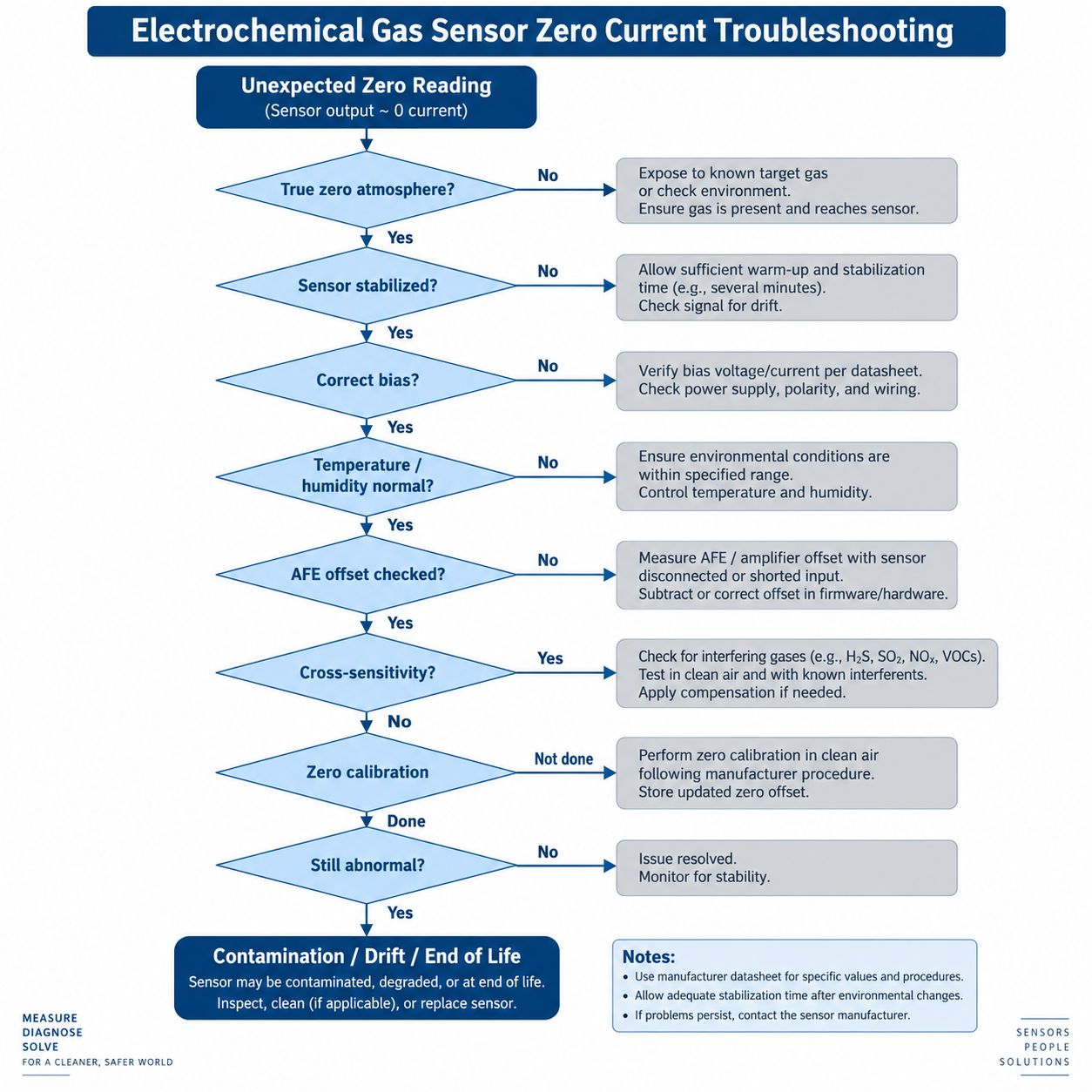
If the detector shows an unexpected zero or baseline condition, use a systematic process.
Step 1 — Verify the Atmosphere
Confirm whether the sensor is really in the specified zero-gas environment.
Do not call a reading “zero current” if target or interfering gas may still be present.
Step 2 — Allow Stabilization
Confirm that the sensor has reached the manufacturer’s required stabilization time.
Step 3 — Check Bias
For biased sensors, verify:
- bias voltage
- polarity
- uninterrupted bias requirements
Step 4 — Check Temperature and Humidity
Compare the environmental conditions with the sensor specification.
Step 5 — Check the Analog Front End
Inspect:
- potentiostat
- TIA
- amplifier offset
- ADC
- PCB leakage
- power supply
Step 6 — Check Cross-Sensitivity
Determine whether another gas can explain the signal.
Step 7 — Perform Zero Calibration if Appropriate
Follow the detector manufacturer’s procedure.
Step 8 — Check Stability
After zero calibration, verify that the baseline remains stable.
Step 9 — Investigate Sensor Condition
If zero remains unstable, consider:
- contamination
- drift
- over-range exposure
- aging
- end of life
The troubleshooting image is a general engineering aid. Always follow the specific sensor and detector manufacturer’s procedure for zeroing and diagnosis.
Common Zero-Current Mistakes
Mistake 1 — Zero Current Means Zero Bias
False.
One is an output current; the other is an electrode operating potential.
Mistake 2 — Zero Current Must Always Be Exactly 0 nA
False.
Real electrochemical sensors can have a specified non-zero baseline range.
Mistake 3 — Positive Zero Current Proves Target Gas Is Present
False.
A baseline offset can exist under zero-target-gas conditions.
Mistake 4 — Negative Zero Current Means Negative Gas Concentration
False.
It is an electrical sign convention, not a physically negative gas concentration.
Mistake 5 — Zero Current Is the Same as Noise
False.
Zero current is a baseline value; noise is rapid fluctuation around the baseline.
Mistake 6 — Zero Current Is the Same as Zero Drift
False.
Zero drift describes how zero changes over time.
Mistake 7 — Ignoring Temperature
Zero output can change substantially across the operating temperature range.
Mistake 8 — Measuring Too Soon After Power-Up or Reconnection
A sensor may require stabilization before its zero can be evaluated.
Mistake 9 — Blaming the Sensor for All Zero Error
The AFE, ADC, PCB and firmware can also contribute.
Mistake 10 — Assuming Every Four-Electrode Sensor Uses the AE the Same Way
The fourth electrode may have a different function depending on the sensor design.
Frequently Asked Questions
What is zero current in an electrochemical gas sensor?
Zero current is the sensor’s baseline electrical output under the specified zero-target-gas test condition.
It may be expressed as current, such as nA, or as a gas-equivalent concentration.
Why does an electrochemical sensor produce current in zero air?
Background electrochemical processes, sensor chemistry, operating bias, environmental conditions and manufacturing variation can produce a small baseline current even without the target gas.
Should zero current always be 0 nA?
No.
The acceptable zero-current range should be taken from the specific sensor datasheet.
What is ppm-equivalent zero current?
It is the apparent target-gas concentration that would produce a current equal in magnitude to the sensor’s zero current.
How do I convert zero current from nA to ppm?
For a sufficiently linear sensor:
ppm equivalent
=
zero current (nA)
÷
sensitivity (nA/ppm)
Use the sensitivity and test conditions appropriate to that sensor.
Can zero current be negative?
Yes.
A negative zero current simply indicates the baseline lies on the negative side of the defined output-current direction.
Is zero current the same as zero drift?
No.
Zero current is the present baseline value.
Zero drift is the change in that baseline over time.
Is zero current the same as sensor noise?
No.
Noise is the rapid random variation around the baseline.
Is zero current the same as zero bias?
No.
Zero bias means the applied potential difference between working and reference electrodes is zero.
A zero-bias sensor can still have non-zero zero current.
Does temperature affect zero current?
Yes.
Temperature can change electrochemical reaction rates, diffusion, electrolyte behavior and baseline output.
Does humidity affect zero current?
It can.
The effect depends on the sensor chemistry and construction.
Does bias voltage affect zero current?
It can.
Bias changes electrode reaction conditions and can influence both target response and background current.
Why does a new electrochemical sensor need stabilization time?
After storage, connection or restoration of bias, the electrochemical cell and readout system may need time to reach a stable operating condition.
Can zero calibration remove zero current?
Zero calibration can compensate for a stable baseline offset at the time of calibration.
It does not remove the underlying electrochemical background current or guarantee that zero will remain stable.
Why do four-electrode sensors have an auxiliary electrode?
In many low-level designs, the auxiliary electrode provides additional information about background and temperature-related zero behavior that can be used for compensation.
Not every four-electrode sensor uses the fourth electrode this way.
Does high zero current increase LOD?
A large zero offset alone does not directly determine LOD.
But unstable zero current, high noise and drift can make low-level detection more difficult.
How do I troubleshoot a gas sensor that will not zero correctly?
Check:
- true zero atmosphere
- stabilization time
- sensor bias
- temperature and humidity
- analog-front-end offset
- cross-sensitivity
- calibration
- contamination
- drift
- sensor age
Final Takeaway
Zero current is one of the most important electrochemical gas-sensor specifications to understand, especially for low-level measurement.
The key distinctions are:
Zero Current
=
baseline sensor output under zero-target-gas conditions
Zero Drift
=
change in that baseline over timeNoise
=
short-term random fluctuation around the baselineZero Bias
=
0 V applied WE–RE bias conditionThese are not interchangeable terms.
A non-zero zero current does not automatically mean the sensor is faulty.
What matters is whether the zero behavior is:
- within specification
- stable
- predictable
- compensatable
and small enough relative to the target-gas signal.
For ppm-level industrial safety, a moderate stable offset may be manageable.
For ppb environmental monitoring, even a small zero-current change can become one of the dominant error sources.
That leads to the most useful engineering rule:
Do not evaluate zero current as one isolated number. Evaluate zero current, noise, drift, sensitivity, temperature behavior and the complete analog signal chain together.
References and Further Reading
- Alphasense — NO₂-A1 Nitrogen Dioxide Sensor
- Alphasense — NO₂-A1 Datasheet
- Alphasense — Sensor FAQs
- Alphasense — Nitric Oxide Sensors
- Analog Devices — AN-1563
- Analog Devices — CN0425
- GasNose — Electrochemical Gas Sensors
- GasNose — 3-Electrode vs 4-Electrode Electrochemical Gas Sensors
- GasNose — Gas Sensor Detection Limit
- GasNose — Gas Sensor Drift
- GasNose — Gas Sensor Cross-Sensitivity
- GasNose — Gas Detector Bump Test vs Calibration
- GasNose — Electrochemical Gas Sensor Bias Voltage
- GasNose — Signal-to-Noise Ratio in Gas Sensors
- GasNose — Temperature Effects on Gas Sensors
- GasNose — Humidity Effects on Gas Sensors