




Temperature can change a gas sensor’s zero baseline, sensitivity, response time, recovery behavior and calibration relationship.
That does not mean every sensor reacts to temperature in the same direction.
For one sensor, sensitivity may increase as temperature rises. Another sensor may show a smaller change, an opposite change, or a strongly nonlinear response. The result depends on:
- sensing technology
- target gas
- sensor chemistry
- diffusion barrier
- internal heater design
- optical components
- electronics
- the exact sensor model
The most important rule is:
A gas sensor being rated to operate across a temperature range does not mean its raw output is temperature-independent across that range.
For electrochemical toxic-gas sensors, Alphasense states that both sensitivity and zero current can change with temperature. Its AAN 110 application note reports typical sensitivity changes of roughly +0.1 to +0.3% per kelvin for the sensor families discussed, while also warning that average curves should not be used as universal software compensation data.
See: Alphasense AAN 110 — Environmental Changes: Temperature, Pressure, Humidity
Analog Devices likewise uses a dedicated temperature sensor and software correction in its CN0396 electrochemical gas-sensing reference design.
See: Analog Devices CN0396 — Dual Electrochemical Gas Sensor with Temperature Compensation
What Parts of a Gas Sensor Reading Can Temperature Change?
Temperature does not create only one generic “temperature error.”
It can affect several independent parts of the measurement chain.
| Parameter | Possible Temperature Effect |
|---|---|
| Zero / Baseline | Output may shift even with no target gas present |
| Sensitivity / Span | The same gas concentration may produce a different signal |
| Response Time | The sensor may respond faster or slower |
| Recovery Time | Desorption, diffusion and reaction kinetics may change |
| Calibration Curve | Slope, intercept or curve shape may change |
| Noise | Sensor chemistry and electronics may behave differently |
| Drift Appearance | Environmental changes can look like drift |
| Lifetime | Repeated extreme temperature stress may accelerate aging |
The key engineering point is:
Temperature can change both the baseline and the gas response, and those two effects are not the same.
Temperature Can Change Zero and Sensitivity Differently
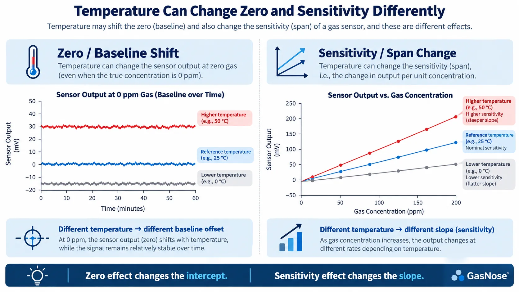
A simple gas-sensor calibration model can be written as:
Y = S × C + bwhere:
Y= sensor outputS= sensitivityC= gas concentrationb= zero / baseline offset
Temperature can affect both S and b.
A more realistic model is therefore:
Y = S(T) × C + b(T)where both sensitivity and zero depend on temperature.
Zero / baseline effect
Suppose no target gas is present:
C = 0 ppmIf temperature changes and the sensor baseline shifts, the instrument may see:
0 ppm actual gas
↓
non-zero electrical output
↓
apparent gas reading
This is a zero effect.
Sensitivity / span effect
Suppose the gas concentration stays constant:
100 ppmbut the sensor signal changes with temperature:
20°C → 100 nA
40°C → 110 nA
The slope has changed.
This is a sensitivity effect.
Alphasense explicitly treats zero-current temperature dependence and sensitivity temperature dependence as separate issues.
For a detailed explanation of electrochemical baseline current, see What Is Zero Current in an Electrochemical Gas Sensor?.
The Direction of Temperature Error Is Not Universal
One of the easiest mistakes is writing:
Higher temperature = higher gas readingas if it were a universal rule.
It is not.
For some electrochemical toxic-gas sensor families, sensitivity may increase with temperature over part of the operating range. But the exact behavior depends on:
- gas
- electrolyte
- electrode chemistry
- diffusion design
- bias
- manufacturer
Even within one manufacturer, different sensor types can show different curves.
Alphasense AAN 110 plots different temperature responses for CO, SO₂, H₂S and NO₂ sensors and explicitly says the average curves should not be used directly for programming compensation.
Similarly, Figaro’s MOS sensor datasheets often publish temperature/humidity dependency curves because response changes are model-specific rather than universal.
See: Figaro TGS826 Product Information
So:
Never copy one generic temperature coefficient into every gas-sensing design.
Stable Temperature vs Rapid Temperature Change
Temperature effects become even more complicated when temperature changes quickly.
A sensor can behave differently under:
stable 0°Cthan during a transition from:
25°C → 0°CWhy?
Because different parts of the instrument have different thermal time constants:
- gas
- housing
- sensor body
- electrolyte
- electrodes
- PCB
- temperature sensor
They do not all reach the new temperature at exactly the same moment.
This can create a temporary output transient.
Rapid Temperature Change Can Cause Transient Errors
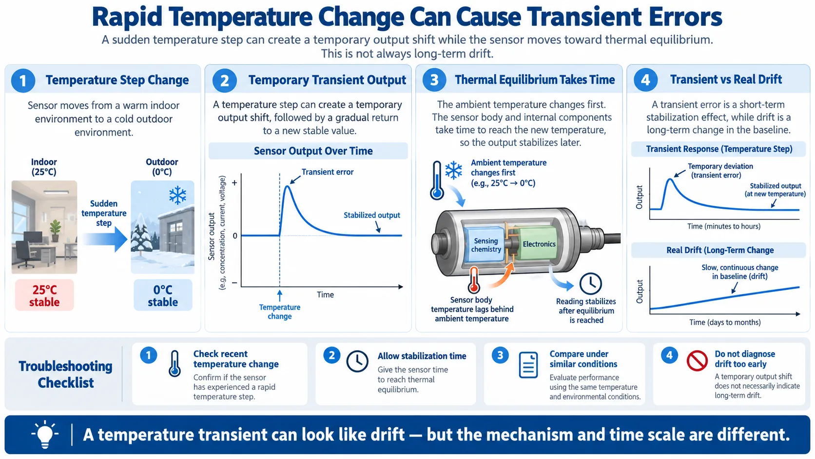
A typical thermal-transition sequence is:
Sensor stable at 25°C
↓
Instrument moved rapidly to cold environment
↓
Ambient temperature changes first
↓
Sensor body and chemistry lag behind
↓
Temporary output shift appears
↓
Thermal equilibrium is reached
↓
Reading stabilizes
Alphasense describes this behavior explicitly for oxygen sensors. Its AAN 005 notes that rapid temperature changes can generate transient current and that faster temperature changes produce larger transient effects.
See: Alphasense AAN 005 — Very Low Temperature Use
This creates an important troubleshooting distinction:
A temperature transient can look like drift, but transient thermal behavior and long-term drift are not the same phenomenon.
For long-term drift mechanisms, see What Is Gas Sensor Drift? Zero Drift, Span Drift & Baseline Drift Explained.
How Temperature Affects Electrochemical Gas Sensors
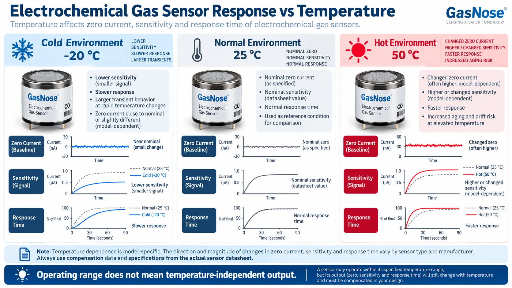
Important: The cold/normal/hot behavior in the illustration is conceptual. The direction and magnitude of actual zero, sensitivity and response-time changes must be taken from the specific sensor datasheet.
Electrochemical gas sensors convert a chemical reaction into electrical current.
A simplified chain is:
Target gas
↓
Diffusion through membrane / capillary
↓
Electrochemical reaction at electrode
↓
Current
↓
Gas concentration
Temperature can affect several stages at once.
Reaction kinetics
Electrode reaction rates are temperature dependent.
Gas diffusion
Diffusion through the sensor’s transport barrier may change with temperature.
Electrolyte properties
Viscosity, conductivity and water balance can change.
Zero current
Baseline electrochemical current may vary.
Sensitivity
The current generated per ppm may change.
Response time
The speed at which the sensor approaches its steady response may change.
This is why electrochemical gas detection often requires temperature characterization rather than a single room-temperature calibration.
Low-Temperature Effects on Electrochemical Sensors
Low temperature can be especially important in:
- refrigerated warehouses
- outdoor winter monitoring
- mining
- cold-chain applications
- gas cabinets in unheated areas
- polar environments
Analog Devices notes that very low temperatures below approximately −30°C can significantly reduce electrochemical sensor sensitivity and responsiveness.
See: Analog Devices — Overcoming the Technical Challenges of Electrochemical Gas Sensing
Possible low-temperature effects include:
Reduced sensitivity
The same gas concentration may produce a smaller electrical signal.
Slower response
Electrochemical reaction and transport processes may slow.
Increased variability
Some sensors show greater unit-to-unit and batch-to-batch variability at very low temperatures.
Alphasense AAN 005 states that sensor-to-sensor variability and temperature dependence increase below −20°C for the oxygen sensors discussed.
Freezing-related behavior
If the sensor approaches the electrolyte freezing region, abnormal behavior and hysteresis may occur.
This is why:
A datasheet operating range should not be interpreted as “identical performance at every temperature.”
High-Temperature Effects on Electrochemical Sensors
Elevated temperature can affect both short-term output and long-term aging.
Possible effects include:
- sensitivity change
- zero-current change
- faster reaction kinetics
- faster response in some sensor designs
- electrolyte evaporation
- seal stress
- long-term baseline shift
Analog Devices notes that brief exposure above 50°C may sometimes be tolerated by certain electrochemical sensors, but repeated high-temperature stress can drive electrolyte evaporation and irreversible degradation.
See: Analog Devices — Electrochemical Gas Sensing Challenges
This creates an important distinction:
Immediate temperature effect
≠
Long-term temperature aging
A sensor may temporarily change output at high temperature and return when cooled.
Repeated thermal stress can also permanently shorten its useful life.
For lifetime mechanisms, see Gas Sensor Lifetime: What Determines Sensor End of Life?.
Temperature Can Change Response Time
Temperature affects not only the final reading but also how quickly the sensor gets there.
Suppose a sensor is specified:
T90 < 30 sThat number is meaningful only under the manufacturer’s stated test conditions.
At a different temperature, T90 may change.
A simplified sequence at low temperature might be:
Gas introduced
↓
Slower transport / reaction
↓
Slower signal rise
↓
Longer T90
But again, the actual change is model-specific.
For response-time fundamentals, see:
How Temperature Affects MOS / Semiconductor Sensors
MOS sensors have another temperature variable that often causes confusion.
There are two different temperatures:
Ambient temperature
The temperature of the surrounding air and sensor package.
Heater / sensing-layer operating temperature
The much higher internal temperature created by the heater.
These are not the same.
Ambient Temperature vs MOS Heater Temperature
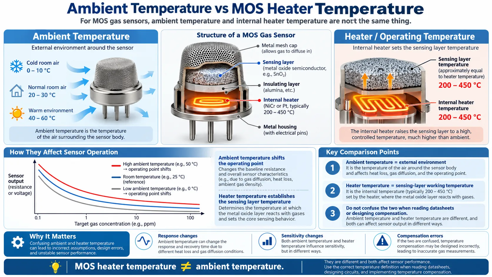
A metal-oxide gas sensor may operate its sensing layer at several hundred degrees Celsius while sitting in room air around 20–30°C.
The heater controls surface chemistry.
Ambient temperature still matters because it changes:
- heat loss
- gas diffusion
- package temperature
- surrounding gas density
- equilibrium operating point
So:
MOS heater temperature ≠ ambient temperature.
Confusing these two can create poor thermal compensation and misleading datasheet comparisons.
Figaro’s TGS826 product information provides a real temperature/humidity dependency curve showing that the sensor’s resistance response changes with ambient temperature and RH.
See: Figaro TGS826 Product Information
For MOS fundamentals, see Semiconductor Gas Sensors.
Why MOS Sensors Have an Optimum Operating Temperature
MOS gas sensing depends on surface adsorption, reaction and desorption.
At a simplified level:
Too cold
- reaction rates may be slow
- the gas may not interact optimally with the sensing layer
Intermediate temperature
- adsorption and reaction may be favorable
- response can increase
Too hot
- desorption may dominate
- gas residence time on the surface may decrease
This can produce an optimum operating temperature for a particular:
- sensing material
- target gas
- catalyst formulation
Therefore:
The best MOS heater temperature is target-gas-specific and sensor-material-specific.
It should not be assumed that a higher heater temperature always produces a larger signal.
Self-Heating Matters When Measuring Temperature
MOS and NDIR sensors may generate their own heat.
This creates another OEM design problem:
Where should you place the external temperature sensor?
Figaro warns that a temperature or humidity sensor mounted too close to a heat-generating MOS sensor can report a value that does not represent the surrounding environment.
See: Figaro — MOS Sensor Cautions
Figaro gives a similar warning for NDIR sensors because their optical source also generates heat.
See: Figaro — NDIR Sensor Cautions
So the design rule is not simply:
Put temperature sensor as close as physically possible.It is:
Measure the temperature that actually governs sensor behavior while avoiding false temperature readings caused by sensor self-heating.
How Temperature Affects Catalytic Bead Sensors
Catalytic combustible sensors use a heated active bead.
The basic mechanism is:
Combustible gas
↓
Catalytic oxidation
↓
Heat
↓
Resistance change
↓
Bridge signal
Ambient-temperature changes can be much larger than the small temperature rise caused by combustible gas.
That is why pellistor systems use a matched compensator bead.
Dräger explains that the active pellistor measures ambient temperature plus heat of combustion, while the non-catalytic compensator responds mainly to ambient temperature. The bridge uses the difference between the two.
See: Dräger — Catalytic Bead / Pellistor Principle
Honeywell similarly describes the inactive bead as compensation for external temperature and humidity changes.
See: Honeywell Gas Book
Catalytic Compensation Is Not Perfect
A compensator reduces temperature effects, but it does not make a catalytic sensor perfectly temperature independent.
Residual differences can remain because of:
- imperfect matching between beads
- catalyst aging
- heater changes
- thermal conductivity effects
- gas-specific oxidation behavior
- electronics
So the correct conclusion is:
Catalytic bead sensors compensate ambient temperature by design, but still need a specified operating range and model-specific calibration data.
For pellistor fundamentals, see Catalytic Bead Gas Sensors.
How Temperature Affects NDIR Gas Sensors
NDIR sensors do not use an electrochemical reaction.
Instead:
IR source
↓
Gas cell
↓
Infrared absorption
↓
Optical detector
↓
Gas concentration
That does not make NDIR temperature independent.
Temperature can affect:
- IR source output
- detector response
- optical filter characteristics
- electronics
- optical path
- gas density and pressure relationships
- condensation risk
Modern NDIR systems therefore commonly use compensation.
Sensirion’s current SCD53 CO₂ sensor, for example, includes integrated humidity and temperature compensation, plus optional pressure correction.
See: Sensirion SCD53
So:
NDIR avoids several electrochemical temperature mechanisms, but the complete optical measurement system still requires environmental compensation.
For the technology itself, see NDIR Gas Sensors.
Ambient Temperature vs Sample-Gas Temperature
In some systems, the gas being measured is not at the same temperature as the detector electronics.
For example:
- heated exhaust
- refrigerated gas
- long sample line
- process pipe
- gas conditioning system
You may therefore have:
Ambient PCB temperature
≠
Sensor-body temperature
≠
Sample-gas temperature
For accurate OEM design, you need to identify which temperature actually influences:
- sensor chemistry
- gas density
- optical absorption
- diffusion
- compensation algorithm
A single temperature value from somewhere on the PCB may not be sufficient.
How Temperature Affects PID Sensors
PID instruments are often discussed more in relation to humidity, but temperature still matters.
Temperature can affect:
- UV lamp behavior
- electronics
- VOC vapor pressure
- sample composition
- condensation risk
A particularly important point is that changing temperature may change the sample itself.
For a volatile compound, warmer conditions can increase vapor pressure and therefore change the amount of VOC reaching the instrument.
This is different from the sensor electronics simply having a temperature coefficient.
The next environmental topic should therefore be treated separately: How Humidity Affects Gas Sensors.
Temperature Can Change the Calibration Curve
Temperature may change:
- intercept
- slope
- sometimes curve shape
At one temperature:
0 ppm   → 0
50 ppm  → 500
100 ppm → 1000
At another:
0 ppm   → 20
50 ppm  → 560
100 ppm → 1110
The difference can involve both:
b(T)and:
S(T)in:
Y = S(T) × C + b(T)This is why temperature dependence is closely related to linearity and calibration.
See Gas Sensor Linearity and Linear Range Explained.
Temperature Can Look Like Drift
Suppose a detector reads:
Morning:
15°C
0 ppm
and later:
Afternoon:
35°C
3 ppm
It is tempting to call this drift.
But if the baseline changes predictably with temperature, the real mechanism may be:
temperature-dependent zero shiftnot long-term drift.
A better diagnostic sequence is:
Unexpected zero change
↓
Check temperature history
↓
Allow thermal stabilization
↓
Compare readings at similar temperature
↓
Then evaluate true drift
This is why environmental conditions should be recorded during calibration and sensor validation.
How Gas Sensor Temperature Compensation Works
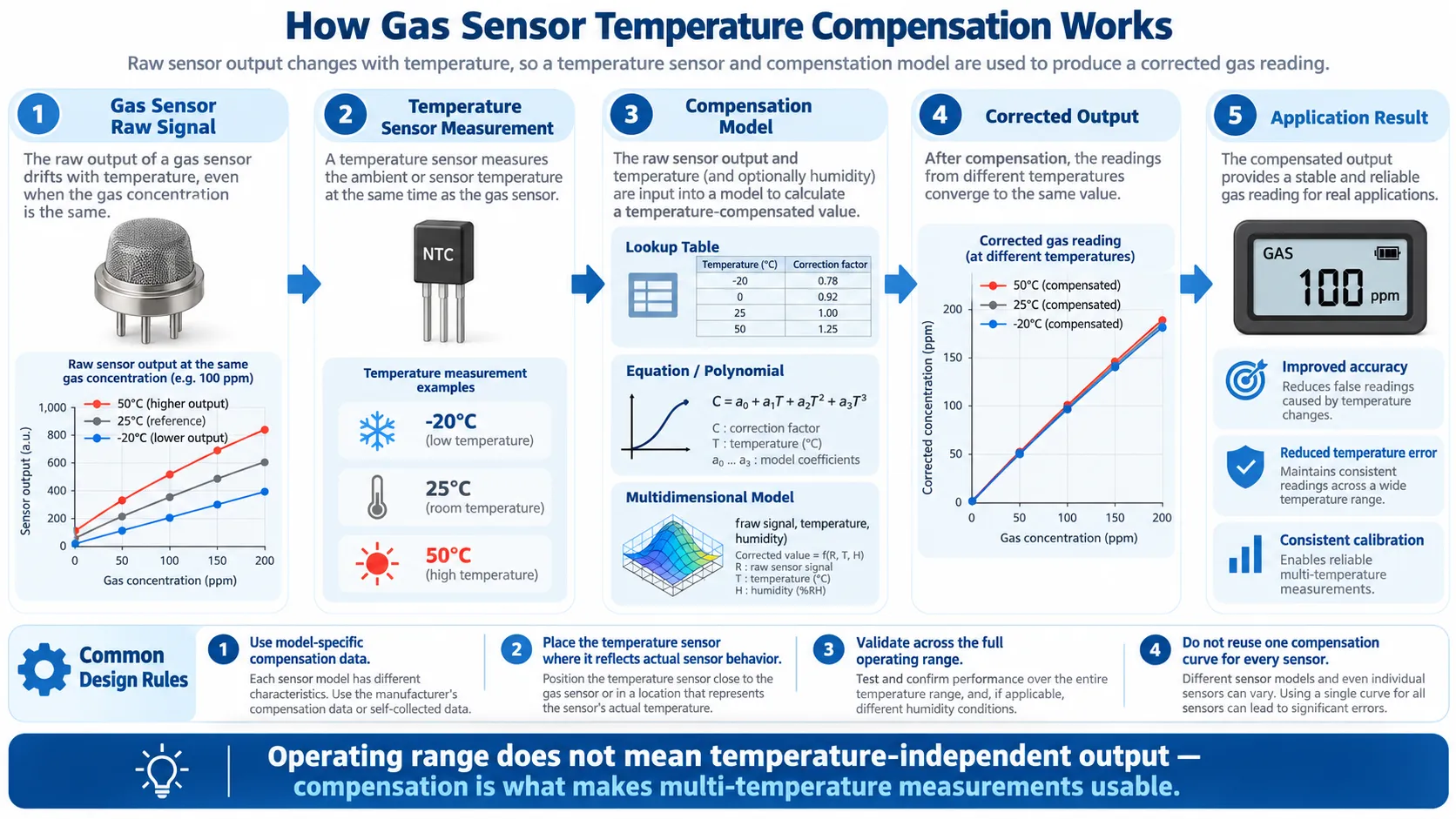
A common compensation architecture is:
Raw Gas Sensor Signal
        +
Temperature Measurement
        ↓
Compensation Model
        ↓
Corrected Gas Reading
Analog Devices CN0396 provides a practical example. It uses an ADT7310 temperature sensor and applies corrections in software using a lookup table or equation.
Common Temperature Compensation Methods
Lookup Table
For example:
Temperature    Correction
-20°C          K1
0°C            K2
20°C           K3
40°C           K4
The firmware interpolates between characterized points.
Polynomial / Equation
A fitted equation can approximate temperature response:
Correction = f(T)Piecewise Model
Different equations can be used across different temperature regions.
Multidimensional Compensation
A more advanced model can use:
Corrected reading
=
f(raw signal, temperature, humidity)
This is useful when temperature and humidity interact.
Compensation Data Must Be Sensor-Specific
A generic curve is rarely enough.
Alphasense AAN 110 explicitly warns that its average family-level temperature curves should not be used directly for programming compensation.
Why?
Because temperature dependence varies with:
- sensor model
- target gas
- production batch
- concentration
- zero behavior
- sensitivity
- aging
Therefore:
Use the correction data supplied for the exact sensor model, or generate validated compensation data for your own system.
Where Should the Temperature Sensor Be Placed?
The answer depends on what you need to measure.
For an electrochemical sensor, Analog Devices recommends placing the temperature sensor close enough to reflect the gas sensor’s thermal environment.
But a MOS or NDIR sensor may generate significant heat.
If a T/RH sensor is placed too close, it may read the sensor’s own heat rather than the surrounding air.
So the more precise engineering rule is:
Place the temperature sensor where it best represents the thermal condition relevant to the compensation model—not simply at the shortest physical distance.
Calibration Temperature Matters
Suppose a sensor is calibrated at:
20°Cbut operates at:
-20°CIf temperature dependence is not compensated, the original calibration may no longer produce the same concentration accuracy.
A useful calibration record should therefore include:
- calibration-gas concentration
- temperature
- humidity
- pressure
- flow
- stabilization time
For high-accuracy applications, validation should cover the actual intended operating environment.
Operating Range vs Compensated Range vs Accuracy Range
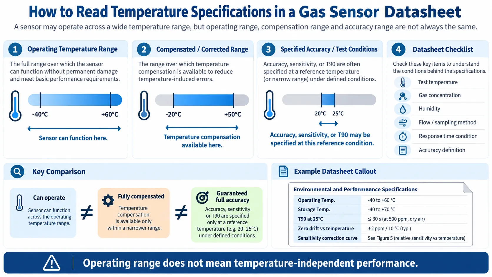
These are often confused.
Operating Temperature Range
The range in which the sensor is intended to function according to the manufacturer’s conditions.
Example:
-40°C to +60°CCompensated / Corrected Range
The range over which a defined correction algorithm or characterization may be available.
Example:
-20°C to +50°CAccuracy / Test Condition
A performance specification may be guaranteed only at:
20–25°Cor under another defined condition.
Therefore:
Can operate ≠ fully compensated ≠ full accuracy guaranteed.
Always check the actual datasheet wording.
Do Not Read One Temperature Number in Isolation
When evaluating a gas sensor datasheet, look for:
- operating temperature range
- storage temperature range
- sensitivity-vs-temperature curve
- zero-vs-temperature specification
- response-time test temperature
- calibration temperature
- humidity condition
- flow / diffusion condition
- compensated range
- guaranteed vs typical values
A T90 value measured at 25°C in dry gas cannot automatically be assumed to apply unchanged at −20°C and high humidity.
Temperature and Humidity Should Be Separated Conceptually
Temperature and humidity interact, but they are not the same environmental variable.
Temperature mainly affects:
- reaction kinetics
- diffusion
- thermal equilibrium
- electronics
- optics
Humidity more directly affects:
- electrolyte water balance
- adsorption
- surface chemistry
- PID water-vapor behavior
- condensation
That is why GasNose treats humidity as a separate engineering topic:
How Humidity Affects Gas Sensors.
How to Test Temperature Dependence Properly
For OEM validation, use a controlled procedure.
Step 1 — Select Relevant Temperatures
Choose temperatures based on the application.
For example:
-20°C
0°C
20°C
40°C
50°C
Step 2 — Control Gas Concentration
Use a stable reference gas.
Step 3 — Control Humidity
Otherwise temperature and RH may change together and you cannot isolate the cause.
Step 4 — Allow Thermal Equilibrium
Do not record immediately after changing chamber temperature.
Step 5 — Measure Zero
At every temperature, record the baseline.
Step 6 — Apply Target Gas
Measure:
- sensitivity
- steady response
- T50
- T90
- recovery
Step 7 — Return Through the Temperature Cycle
This helps reveal hysteresis or thermal-history effects.
Step 8 — Test Multiple Sensors
One sensor cannot represent the entire production population.
Step 9 — Build the Compensation Model
Use:
- lookup table
- polynomial
- piecewise model
- multidimensional model
as appropriate.
Step 10 — Validate With Independent Conditions
Do not validate only at the same points used to fit the model.
Common Temperature-Related Gas Sensor Mistakes
Mistake 1 — Operating range means constant output
False.
The sensor may operate across the range while zero, sensitivity and response time still change.
Mistake 2 — Higher temperature always means a higher reading
False.
Direction and magnitude are model-specific.
Mistake 3 — Every electrochemical sensor uses the same coefficient
False.
Temperature behavior varies by sensor chemistry and target gas.
Mistake 4 — Only sensitivity changes
False.
Zero can also change.
Mistake 5 — Temperature affects only accuracy
False.
Response and recovery can also change.
Mistake 6 — A fast thermal transient is the same as drift
False.
Thermal transients occur while the sensor approaches equilibrium; drift is a longer-term change under comparable conditions.
Mistake 7 — MOS ambient temperature equals heater temperature
False.
The heater temperature can be hundreds of degrees above ambient.
Mistake 8 — A catalytic compensator removes all temperature error
False.
It reduces ambient thermal effects but does not eliminate every residual error.
Mistake 9 — NDIR is temperature independent
False.
Optical sources, detectors, electronics and gas conditions still require characterization.
Mistake 10 — Put the temperature sensor as close as possible in every design
False.
Self-heating can make a nearby temperature sensor unrepresentative of actual ambient conditions.
Frequently Asked Questions
Does temperature affect gas sensor readings?
Yes.
Temperature can change zero, sensitivity, response time and calibration behavior. The exact effect depends on sensor technology and model.
Why does a gas detector reading change with temperature?
Temperature can change the physical and chemical processes that produce the sensor signal, as well as the electronics used to measure it.
Does cold weather make gas sensors less sensitive?
Some electrochemical sensors show reduced sensitivity or slower response at very low temperature, but this should not be generalized to every sensor.
Use the model-specific datasheet.
Can temperature cause a false gas reading?
Yes.
A temperature-dependent baseline shift can create an apparent gas reading even if the true target concentration has not changed.
Does temperature affect zero current?
Yes, especially for some electrochemical sensors.
The magnitude and direction are model-specific.
Does temperature affect sensitivity?
Yes.
The signal generated per unit gas concentration can change with temperature.
Does temperature affect gas sensor response time?
Yes.
Transport and reaction processes can become faster or slower as temperature changes.
What is gas sensor temperature compensation?
It is the use of temperature measurements plus model-specific correction data to reduce temperature-induced measurement error.
How is temperature compensation calculated?
Common methods include:
- lookup tables
- equations
- polynomials
- piecewise models
- multidimensional models
Can I use the same compensation curve for every sensor?
No.
Use data for the exact sensor model and validate it in the intended system.
What is the difference between operating temperature and compensated temperature?
Operating temperature is where the sensor can function under specified conditions.
A compensated range is where the manufacturer or system provides a defined temperature correction.
These may not be identical.
Does temperature affect MOS gas sensors?
Yes.
Ambient temperature affects heat loss, gas transport and surface chemistry, while the internal heater establishes the sensing-layer operating temperature.
Does temperature affect catalytic LEL sensors?
Yes.
Matched active and compensator beads reduce ambient temperature effects, but residual temperature dependence remains.
Does temperature affect NDIR sensors?
Yes.
The optical source, detector, electronics and gas conditions all have temperature dependence, so compensation is commonly used.
Should I calibrate a gas detector at its operating temperature?
For high-accuracy work, calibration and validation should reflect the actual operating environment where practical.
Always follow the instrument manufacturer’s procedure.
Can rapid temperature changes cause temporary sensor errors?
Yes.
Rapid thermal transitions can create transient output shifts until the sensor reaches thermal equilibrium.
Can extreme temperature shorten sensor lifetime?
Yes.
Repeated high-temperature stress, freezing, electrolyte changes, condensation and other thermal effects can accelerate aging or damage some sensor types.
Final Takeaway
Temperature affects gas sensors in more than one way.
Remember:
Temperature can change zeroTemperature can change sensitivityTemperature can change response timeTemperature can change the calibration relationshipand:
Operating temperature range
≠
temperature-independent performance
A robust gas-sensing system therefore needs:
- model-specific temperature characterization
- appropriate sensor placement
- thermal stabilization
- validated temperature compensation
- calibration under defined conditions
- environmental data recorded during troubleshooting
The core engineering rule is:
Do not ask only whether a gas sensor can operate at a given temperature. Ask how its zero, sensitivity, response time and accuracy change at that temperature.
References and Further Reading
- Alphasense — AAN 110: Environmental Changes: Temperature, Pressure, Humidity
- Alphasense — AAN 005: Very Low Temperature Use
- Alphasense — Sensor FAQs
- Analog Devices — CN0396: Dual Electrochemical Gas Sensor with Temperature Compensation
- Analog Devices — Overcoming the Technical Challenges of Electrochemical Gas Sensing
- Figaro — TGS826 Product Information
- Figaro — MOS Sensor Cautions
- Figaro — NDIR Sensor Cautions
- Dräger — Catalytic Bead / Pellistor Principle
- Honeywell — Gas Book
- Sensirion — SCD53 CO₂ Sensor
- GasNose — Gas Sensor Drift
- GasNose — Gas Sensor Response Time: T50 vs T90
- GasNose — Gas Sensor Response Time vs Recovery Time
- GasNose — Electrochemical Gas Sensor Zero Current
- GasNose — Gas Sensor Linearity and Linear Range
- GasNose — Gas Sensor Repeatability vs Accuracy
- GasNose — Gas Sensor Lifetime
- GasNose — Gas Sensor Saturation and Over-Range
- GasNose — Humidity Effects on Gas Sensors
